A fiber-optic splitter, also known as a beam splitter, is based on a quartz substrate of an integrated waveguide optical power distribution device, similar to a coaxial cable transmission system. The optical network system uses an optical signal coupled to the branch distribution. The fiber optic. These unassuming devices enable a single optical signal to be divided into multiple paths, making them indispensable for sharing network resources efficiently—from residential FTTH (Fiber-to-the-Home) connections to large-scale telecom backbones. Optical splitter. Fiber optic splitter is a passive optical device used to distribute optical signals, which can divide input optical signals into multiple outputs to meet the fiber optic access needs of multiple terminal devices. Optical splitters are a very important component in fiber optic links, widely used in. They are devices that split an incident light beam into several light beams at certain splitting ratios. The role of these splitters in optical networks is crucial as they allow a single optical signal to be shared among many users, thereby enhancing the efficiency and capacity of the network. Each type serves specific applications, enabling efficient use of optical infrastructure.
[PDF]
Buyers typically pay for fiber laying by combining material costs, labor time, and permitting plus trenching or aerial support fees. The main cost drivers are trench depth, fiber count and type (single-mode vs multi-mode), conduit requirements, and local permitting rules. This guide walks through each stage of underground fiber installation—from route planning and conduit selection to splicing, termination, and testing—to help ensure long-term network performance and reliability. A successful underground fiber optic cable installation begins with careful planning. Installing underground fiber optic cables is critical to establishing high speed internet infrastructure that delivers reliable connectivity for businesses nationwide. Unlike traditional copper systems, fiber optic cables require specialized handling techniques and precise installation methods to. Underground cables are pulled in conduit that is buried underground, usually 1-1. 2 meters (3-4 feet) deep to reduce the likelihood of accidentally being dug up. From the initial site survey to the final fiber to the home (FTTH) connection, every stage requires careful planning, coordination, and. This comprehensive guide walks through the essential steps and best practices for successful underground fiber optic cable deployment, ensuring optimal performance and longevity of your network installation. This article provides cost.
[PDF]
The scheme is a blend of 2. 5G/3G/4G wireless public network communication technology and LoRa /Zigbee/433 MHz wireless Internet collection technology, provide WiFi hotspots, Ethernet and RS232/RS485 and I/O interface, realize the wireless data transmission . The scheme is a blend of 2. This article will delve into how the 4g lte routers supports distribution automation in smart grids, revealing. Proposed in this paper, the fusion of 2. The utilities sector is no exception to this trend and will see global spending on dedicated cellular networks grow at. Abstract— Southern California Edison is evaluating a new switch automation technology, referred to as the Remote Integrated Switch (RIS). The RIS includes a new control and communication scheme forming a distribution automation application with advanced functionality. The previous RIS system. Honeywell's RTU2020 is a versatile solution for today's remote applications. This powerful controller can be paired with our Cloud Link 4G Cellular Modem to help industrial operators better utilize key distributed production assets. Across the global industrial sector, it is more important than. Remote Terminal Units (RTUs): These are electronic devices used to monitor and control field equipment, such as switches and transformers, in a distribution automation system. Cellular communications can be used to transmit real-time data from the RTUs to the control center, allowing for remote.
[PDF]

Power over Ethernet (PoE) does not work directly over fiber-optic cables because fiber-optic cables are designed to transmit data using light, and they do not conduct electricity. PoE requires copper cables (such as Cat5e, Cat6, or Cat6a) to deliver both power and data. Power over Ethernet (PoE) is a useful technology in powering remote devices, but as we see with any copper network cable, the challenge lies in the limited distances of UTP cabling. The maximum distance for Power over Ethernet (or any network data transmission) is 100 meters or 328 feet. However, selecting the right PoE switch requires careful consideration of factors such as projected organizational growth and device. In the field of network cabling and device power supply, Power over Ethernet (PoE) technology has become widely adopted due to its ability to transmit both data and power over a single Ethernet cable. In industrial environments, industrial switches are key network devices that are adapted to harsh. IP cameras that are part of a modern surveillance system are deployed using PoE technology that involves the use of copper based network cabling like CAT5e or CAT6 that has a data transmission limit of 100m (328ft). While that is adequate for installations for a home or small business, large scale. They have dual-port choices and are easy to set up. Media converters work well in many places. You do not have to worry about distance.
[PDF]

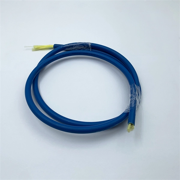
Fiber optic cable can be run anywhere from 300 meters up to 80 kilometers (roughly 50 miles) depending on the cable type, transceiver used, and network standard. For most enterprise or data center applications using multimode fiber, the practical limit sits between 300 m and 550 m. Fiber optic cable transmission distance is determined by two primary physical factors that affect signal quality as light travels through the fiber medium. The greater the distance, the greater. Many factors decide the fiber cable distance, but the key factors include the below six aspects. Attenuation First is the attenuation of the optical fiber. OM2 extends this to 82 meters. OM1 fiber and OM2 fiber don't support these higher speeds. OM5 fiber matches OM4 at. For instance, without amplifiers, single-mode fiber can reach 50-60 miles and can support data rates of 1 Gbps or 10 Gbps. With amplifiers, such as Erbium-doped fiber amplifiers (EDFAs), the distance can be extended to 600 miles or more, and even further with additional amplifiers for long-haul.
[PDF]

A: Single mode fiber can typically transmit up to 160 km, and with dispersion compensation, it can exceed 200 km. Q: How far can multimode fiber go? A: The transmission distance of multimode fiber depends on the fiber type and data rate. However, for long-distance applications (e., metro and backbone networks), single mode fiber provides lower attenuation and future-proof scalability, resulting in lower long-term operational costs. For example, a fiber optic cable with a distance of 1km supports a bandwidth of 500MHz, while a fiber optic cable with a distance of 2km can only support a bandwidth of 250MHz. There are three main reasons for this: First, high-bandwidth. In the complex landscape of fiber optic infrastructure, selecting the right cable type—single-mode (OS1/OS2) or multimode (OM1/OM2/OM3/OM4/OM5)—can define a network's speed, reach, and cost-effectiveness. This guide dissects their technical nuances, evolution, and real-world applications. Fiber optic cable transmission distance is determined by two primary physical factors that affect signal quality as light travels through the fiber medium. Minimum Distance for Single-Mode Fiber: No Specific Limitation. Single-mode fiber is widely used in. Single-mode fiber (SMF): Uses a single light path, enabling it to transmit data over longer distances with less signal loss.
[PDF]
Langzhi China is a professional FTTH equipment manufacturer specializing in GPON/EPON OLT, ONU/ONT, and SFP modules compatible with Huawei & ZTE. Factory-direct pricing, global shipping, OEM/ODM available. Shop now for reliable fiber optic network solutions. Hengtong Group was established in 1991 and is the largest optical cable manufacturer in China. They are committed to the development of comprehensive cabling systems and have established a complete optical communication product chain, from optical fiber to fiber optic cables to optical devices. We will analyze the. Fiberlink is a professional fiber optic cable manufacturer, producing over 20,000 fiber optic products annually and offering a wide range of solutions, including connectors, patch cords, and cabling systems. With ISO9001 certification and a dedicated engineering team, Fiberlink positions itself as. Here are the top-ranked fiber optic cable companies as of May, 2026: 1. Charlton Precision Products, Inc. WIN SOURCE ELECTRONICS, 3. Megladon Manufacturing Group, Ltd. This guide ranks China's top 10 fiber optic cable manufacturers for 2025, based on market share, production capacity, innovation, and global reach. The list prioritizes companies with strong export performance (to 100+ countries) and compliance with international standards like ITU-T G.
[PDF]

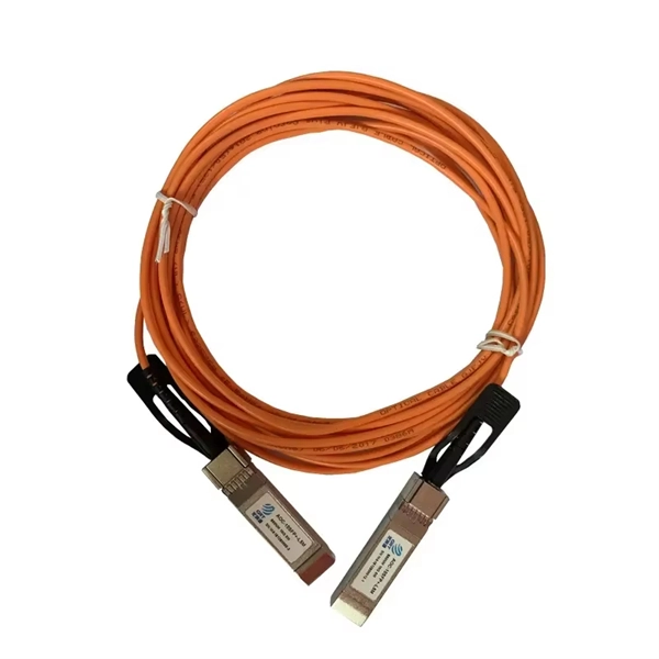
Its typical transmission distance is 20km or 40km. For instance, some ethernet switch manufacturers refer to the 1000BASE-LH SFP as the 1G 1310nm 40km SFP transceiver, which indicates the module's transmission distance and wavelength. The 10G SFP+ dual-fiber optical module is a small pluggable optical transceiver that adopts a dual-fiber bidirectional design. It completes signal transmission (Tx) and reception (Rx) through two independent optical fibers, ensuring the stability and reliability of signal transmission. An SFP (Small Form-factor Pluggable) module transmits data over fiber using specific wavelengths and power levels, which directly influence how far the signal can travel before degradation occurs. This is why two. If the optical module works at a wavelength near 850nm (880nm) or 910nm (940nm), then the module is a multi-mode fiber (MMF) optical transceiver, and if the working wavelength is 1310nm or 1550nm, it is a single-mode fiber (SMF)optical module. Generally, the maximum transmission distance(generally. The transmission distance of optical transceiver modules is divided into short distance, medium distance, and long distance. A 1-core module uses a single fiber core for data transmission, while a 2-core module uses two cores. o Think of a highway. Chromatic dispersion This is a key factor affecting single mode fiber distance.
[PDF]
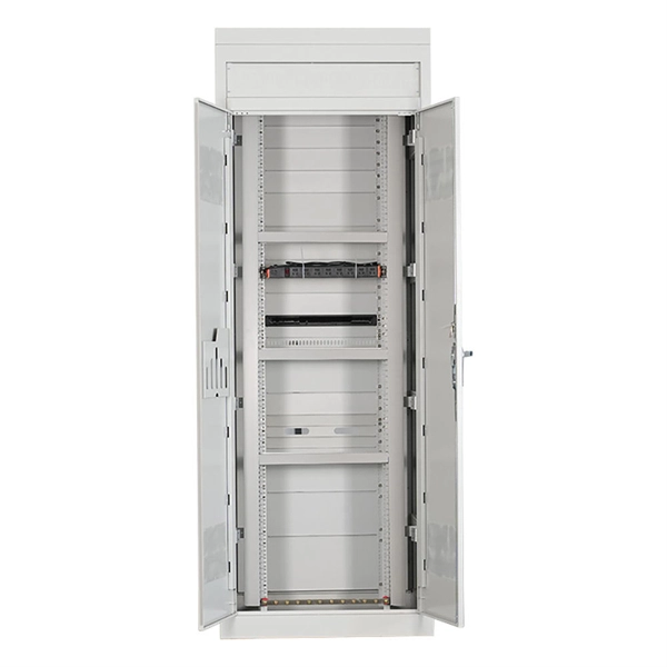
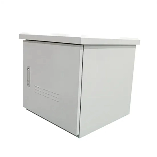
Free electrical calculators for wire sizing, voltage drop, load calculations, conduit fill & power factor. NEC compliant tools for electricians & engineers. In this guide, we'll break down everything you need to know to install a distribution box correctly and confidently. Choose the right box based on environment (indoor/outdoor), load capacity, and durability. Check for proper IP/NEMA ratings and material quality. Ensure safe placement: install in. Professional electrical wire sizing tool based on National Electrical Code (NEC) standards. Calculate proper wire gauge, voltage drop, and ampacity for safe electrical installations. Input your electrical parameters to get accurate wire size. Pro Insight: A well-planned distribution box feels like a silent partner—you only notice it when something's wrong. Our goal? Make sure you never notice it. Before we dive into calculations, let's get familiar with a few essentials: 1. Create accurate bids and win more projects with automated formulas. The sizing requirements for pull boxes, junction boxes, handhole enclosures, and conduit bodies exist to prevent conductor insulation damage. Those requirements are in 314. 28, and they apply to all conductors 4 AWG and larger (Fig. To illustrate how these requirements prevent conductor. Estimate wire ampacity with derating factors for temperature and conduit fill. Reference tool based on NEC guidelines. It is NOT a substitute for professional.
[PDF]
Calculate lighting loads, branch circuit requirements, and illumination levels per NEC Article 210 and 220 standards. Essential tool for commercial and residential lighting system design. Calculations are for reference only. Always verify against NEC and local codes before installation. Consult a. Free electrical load calculation tool for residential and commercial buildings. Your Project's Total Power Demand This isn't just adding up wattages randomly. Think of your home as a busy kitchen—not every appliance runs at once. Proper load calculations ensure that electrical systems are safely designed with adequate capacity for present and future needs. What is Electrical Load. Calculating Circuits for Lights and Sockets in Commercial Fit-Out Projects: A Project Manager's Guide The management of a commercial fit-out involves many tasks, and one of the most important activities is ascertaining the number of electrical circuits required for lights and sockets. Proper. Any underlined text denotes a change to the Code for the 2020 NEC. 3 lists references for branch-circuit calculations for.
[PDF]

The formula for calculating electrical box size is: . The formula for calculating electrical box size is: . Free electrical load calculation tool for residential and commercial buildings. Calculate service entrance sizing, panel loads, demand factors, and ensure NEC Article 220 compliance. Important: Load calculations must comply with NEC Article 220 and local codes. Always verify calculations with a. How to choose a distribution box of the right size for a project based on load current? If you're like most electrical professionals, picking the right distribution box for your project can feel like navigating a maze. I've been in those shoes - staring at spec sheets, worrying about. The National Electrical Code (NEC) specifies minimum box sizes based on wire gauge and quantity. Proper sizing ensures safety, ease of maintenance, and compliance with regulations. This calculator helps you determine the minimum required box volume based on the number of wires, devices, ground wires, and clamps involved. This ensures compliance with electrical codes and prevents overcrowding. Choose a standard or custom box volume watch capacity update with clear pass or fail status plus tips examples CSV and PDF export for documentation Works for common sizes supports.
[PDF]
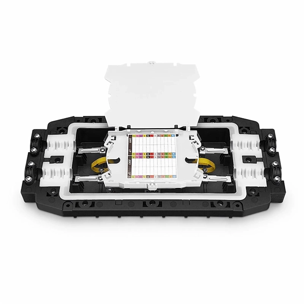
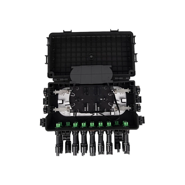
Calculate split loss, excess loss, and terminations for any ratio quickly today. See power budget impact instantly, then download a CSV or PDF summary. Use 2×N when two inputs feed the same distribution stage. Common values: 2, 4, 8, 16, 32, 64. Wavelength is recorded in. Fiber optic joints or terminations are made two ways: 1) splices which create a permanent joint between the two fibers or 2) connectors that mate two fibers to create a temporary joint and/or connect the fiber to a piece of network gear. Either joining method must have three primary characteristics. Optical fiber channel insertion loss is the decrease in optical power that occurs when an active transmitter is linked to an active receiver via terminated, optical fiber cables and patch cords and may include splice points and optical couplers. In general, loss is the natural decay of a signal. Telcordia and TIA allow a 0. 3 dB maximum splice loss. Connector loss is always measured as a mated pair. ITU & IEC allow 0. Splitter loss values are "Typical" and include a connector in and out. These terminations must be of the right style, installed in a. In this lesson, a long and very important one, you will learn about fiber splicing and termination. Wavelength is recorded in outputs for documentation.
[PDF]

Homeowners and businesses typically pay for fiber optic cable installation based on distance, conduit needs, and labor. The main cost drivers include material type, run length, trenching or aerial work, and any required permits or inspections. Whether you're running fiber to a home or a data center, here's exactly what contractors are charging in 2026. What is the real cost of fiber optic cable per foot in 2026? After analyzing 40+ U. fiber projects, we've assembled current material rates, labor burdens, and hidden fees. This guide provides clear cost estimates, price ranges. Buyers typically pay for fiber laying by combining material costs, labor time, and permitting plus trenching or aerial support fees. The initial cost of installing fiber optic cables can vary depending on the chosen installation method. Cost of Laying Fiber Optic Cable in the U. – One and Done Prep Buyers typically see total project costs driven by line length, trenching, permits, and labor. The price ranges reflect both ongoing improvements in fiber deployments and regional differences in permitting and crew rates. The. BroadbandUSA collected information about network construction expenses to increase awareness of the costs associated with deploying a broadband network. This information can help project leaders engage with providers and network operators in their area. This data is based on cost information.
[PDF]
In this guide, we'll break down everything you need to know to install a distribution box correctly and confidently. Choose the right box based on environment (indoor/outdoor), load capacity, and durability. Check for proper IP/NEMA ratings and material quality. An electrical sub panel is a secondary distribution point for power, designed to expand capacity and organize circuits within a property. It operates downstream from the main service panel, the primary connection point to the utility power grid. The sub panel is a smaller breaker box that receives. A subpanel is essentially a smaller electrical panel that is connected to the main electrical panel in your primary building. This. The customer shall immediately notify Con Edison of any suspected leakage or escape of gas by calling the company's toll-free hotline 1-800-75CONED or 1-800-752-6633. It's the Law! Call before you dig! Much of the Con Edison equipment that transmits and delivers energy is under the ground. Proper sub panel wiring is a fundamental skill for any licensed electrician, critical for safely expanding a building's electrical capacity. Key compliance points include performing an accurate panelboard. E-mail: Customer_Service@aep. com Phone numbers: Arkansas Customer Service Phone: 888-216-3523 AEP Texas Customer Service Phone: 877-373-4858 Indiana Michigan Power Customer Service Phone: 800-311-4634 Kentucky Customer Service Phone: 800-572-1113 Southwestern Power Customer Service Phone:.
[PDF]