Optical return loss is the amount of light that is reflected back to the source, this reflected light is measured at each connector and splice at each point over the entire fiber link. This is always measured in dB (decibels) and will be displayed as a negative number. The closer the number is to. The polish of a singlemode fiber endface plays a significant role in reflectance. Understand what you need before you specify. The Institute of Electrical and Building the ORL story Electronics Engineers (IEEE) recently Within a fiber-optic channel or path-released new specifications within way. Optical Return Loss (ORL) in fiber optics refers to the amount of light that is reflected back toward the source in a fiber link. ORL is usually expressed in decibels (dB) as a positive value, with. Return loss (RL) is also called reflection loss. When high-speed signals enter or exit a part of an optical fiber, such as an optical fiber connector, discontinuity and impedance mismatch may cause reflection, which is the return loss of an optical fiber. Poor ORL is commonly caused by dirty connectors, poor splices, mismatched connector types, or damaged fibers. ORL is measured using ORL meters. Home Coherent Optics Optical Return Loss (ORL) Explained Comprehensive Guide to Understanding and Managing Back-Reflections in Fiber Optic Systems What is Optical Return Loss (ORL)? Optical Return Loss (ORL) is a critical parameter in fiber optic systems that quantifies the amount of light.
[PDF]

The typical specification range of return loss of a fiber connector is -15 dB to -60 dB. Return loss is also known as reflection loss. It indicates the amount of signal reflected back to the transmitting end. Return loss refers to the power loss caused by the reflection of part of the signal back to the signal source during transmission due to the discontinuity of the transmission. Insertion loss, also known as attenuation, is the loss of optical power that occurs when light passes through a fiber optic connector. It is caused by factors such as misalignment, air gaps, and imperfections in the connector components. The lower the insertion loss, the better the performance of. Reflectance (which has also been called "back reflection" or optical return loss) of a connection is the amount of light that is reflected back up the fiber toward the source by light reflections off the interface of the polished end surface of the mated connectors and air. It is also called. Insertion Loss (IL) is the amount of optical power lost as the signal travels from one point to another in a fiber optic link, usually across connectors or splices. Formula for. In optical fiber communication, insertion loss and return loss are two important parameters to evaluate the quality of interfaces between some optical fiber components, such as optical fiber connector, fiber patch cable, pigtail fiber, etc. While it's natural to have.
[PDF]

Dispersion of an optical fiber directly affects the bandwidth and distance capability of the fiber optic link and reduces its efficiency. The higher the dispersion, the lower the potential data rate and transmission distance. Fiber optic cable transmission distance is determined by two primary physical factors that affect signal quality as light travels through the fiber medium. The greater the distance, the greater. With amplifiers, such as Erbium-doped fiber amplifiers (EDFAs), the distance can be extended to 600 miles or more, and even further with additional amplifiers for long-haul applications. In this guide, we'll explore how fiber optic cables function, the maximum distances for different types of fiber optics, and tips for. Fiber optics transmits information by sending light signals through thin strands of glass. While this technology offers higher speeds and longer distances than traditional copper wiring, physical limitations impose distance constraints. Light pulses degrade as they travel over long spans, primarily. The maximum distance a fiber optic cable can transmit data reliably is influenced by several key factors, primarily the inherent properties of light and the physical characteristics of the fiber itself. Understanding these limitations is essential for designing efficient and robust internet.
[PDF]
Fiber optic transmission distance varies based on fiber type, environmental conditions, and equipment selection. This guide explores the key factors affecting fiber optic transmission distance and provides practical selection guidelines for a stable and cost-effective network. Receiver Sensitivity Higher receiver sensitivity means that it can detect weaker optical signals. Even if the optical signal power is low, the receiver can still detect and decode the signal correctly, extending the transmission distance of fiber optic communication. Another consideration is that. Fiber optic cable transmission distance is determined by two primary physical factors that affect signal quality as light travels through the fiber medium. For most enterprise or data center applications using multimode fiber, the practical limit sits between 300 m and 550 m. Single-mode. Estimate one-way and round-trip timing for fiber runs, optics, and active hops in home labs and backbone links. Direct point-to-point links with OS2 single-mode 1310 nm typically use 10 km+ of practical reach. Configuration type Fiber profile Route length Measured in feet for imperial mode. Apply a waste factor based on site practice. Click Calculate to see totals and the breakdown. Use the export buttons to share results. For critical links, verify on drawings and allow extra for rework. Fiber length takeoff starts with a measured route. Break the pathway into segments for tray runs.
[PDF]
Nigerian mobile operators have deployed a total of 77, 235. 5km of fibre (On-land and Submarine) as at December 2022, according to a report by the Nigerian Communications Commission (NCC). According to NCC Nigerian Communications Commission said, with the continued deployment of the past few years, Nigeria's national optical fiber cable length is close to 40,000-kilometer, which greatly improve the quality of broadband Internet connections in the country. The report said that 49,367. 2km was deployed on land as terrestrial fibre optics cable, while 27,868. 3km was. Minister of Communications, Innovation and Digital Economy, Dr Bosun Tijani. The Federal Government is targeting the planned deployment of 90,000 kilometres of fiber-optic cable across Nigeria to start within the next six months. Project BRIDGE is the establishment of a Special Purpose Vehicle (SPV) aimed at deploying at least 90,000 km of Fiber Optic cables as Nigeria's core connectivity Infrastructure and national backbone for universal access to Information and Communication Technology (ICT) across Nigeria, under a. The Federal Government has announced an ambitious plan to lay 90,000 kilometres of fibre optic cable across Nigeria as part of efforts to deepen internet access and digital inclusion, a move it says is critical to delivering the dividends of democracy and boosting economic development. A critical component of the plan involves the establishment of a Special Purpose Vehicle (SPV).
[PDF]

LC Connectors: Press the latch mechanism and gently pull the connector out. This guide outlines proper methods to safely remove fiber optic cable from modems in your home or office. As an experienced technology writer who has covered broadband advancements for over a decade, I aim to provide readers with trustworthy instructions endorsed by industry experts. Having. Unplugging a fiber optic cable from a modem is a task that requires careful handling to avoid damaging the delicate fibers within the cable. Fiber optic cables are different from traditional copper cables, as they use light to transmit data, and the connectors are more sensitive. This is a popular video tutorial that is often requested by viewers. Fiber optic cables are delicate and require specific handling procedures to maintain their performance and longevity. Is this something that requires a Verizon support tech or can I do it? If so is it as simple as disconnecting and reconnecting or would I have to call support to "reinitiate" my setup. Not my pic, but didn't feel like moving the. Unicom's Wireless Router is a multi-function device providing the following services: • Shared Broadband Internet Access for all LAN users. Page 5 All manuals and user guides at all-guides. com • Virtual Servers. This feature allows Internet users to access Internet servers on your LAN.
[PDF]
Find all you need for professionally buying wavelength division multiplexing devices: a comprehensive expert-curated directory of suppliers, scientific and technical background information, and an interactive AI-based tool with guidance for a structured decision process. A multiplexer is a digital device that combines several inputs into one line. The number of input lines to be multiplexed depends on the select lines' capacity. A mux makes it easier to convey data in systems that need multiple signals to be transmitted over a single medium. You appear to be visiting. We produce fiber-coupled Wavelength-Division Multiplexing (WDM) devices that combine (Mux) or separate (DeMux) multiple wavelength channels into or from a single optical fiber. Two types are available: integrated arrayed waveguide gratings (AWG), offering low cost, compact size, and precise ITU. WDM AWG CWDM4 module is based on silicon chip technology. It has compact, easy-to-assemble structure and good reliability. It can replace TFF (thin film filter) type CWDM. It is widely used in 40G and 100G high-speed active optical modules for optical signal Mux and Demux, such as QSFP+, QSFP28. wdm module is a truncation for Wavelength-Division Multiplexing, and is currently one of the most broadly involved innovation for high-limit optical correspondence systems. At the transmitter side, wdm module has numerous optical transmitters - each emanating at an alternate frequency -.
[PDF]

Optical Fiber Communication (OFC) revolutionizes modern telecommunications, enabling rapid data transfer across long distances with minimal signal loss. This comprehensive review explores OFC's historical evolution, core principles, components, and versatile applications. It traces OFC's. Additionally, optical fiber is lightweight and less susceptible to noise (no electromagnetic induction). Optical fiber consists of a cylindrical core that propagates light and a concentric cladding that surrounds it. The cladding's refractive index is slightly smaller than that of the core, which. Fibre optics and optical communications is the use of thin strands of glass for sending information encoded into light over long distances. Total internal reflection prevents light inserted into one end of the fibre from escaping through the sides. Keywords: Optical fibers, communication systems, data. Figure 1: Illustration of the inverse-square law of light intensity – the light's intensity diminishes with the square of the distance, which free-space optical signals must overcome (leading to very weak reception at long range) Figure 1 illustrates how light intensity decreases as distance.
[PDF]
The securing, storing and supporting of fiber optics and splices makes up an important step of fiber optic deployments in the field. Whether connecting to aerial or underground cables, telecommunication.
[PDF]
In this guide, we'll walk you through the entire process of preparing fiber optic cable for splicing and termination to fiber connectors. We'll explore the necessary tools, safety precautions, and step-by-step procedures for cable connectors, mechanical and fusion. In this guide, you will find a chronological description of the fusion splicing process, the principal technical standards, and answers to the real-life questions network engineers and procurement teams may have. Therefore, we will also touch on cost factors, risk management, and best practices in. In this guide, we cover the basics of fiber optic splicing, how to perform splicing using two different methods, and finally some best practices to perform good fiber splicing. What is Fiber Optic Splicing and Why is it Needed? – #1. Two types of splices are used in fiber optic cabling one is Mechanical the other is Fusion. Before jumping into the physical steps, it's important to understand the two primary methods of fiber splicing: fusion splicing and. Learn how to splice fiber optic cable step by step in this complete guide! In this video, you'll see the full fiber splicing process — from fiber preparation, cleaving, and fusion splicing to final testing. For network managers and technicians, a poor splice can lead to significant signal degradation, network downtime, and costly troubleshooting.
[PDF]

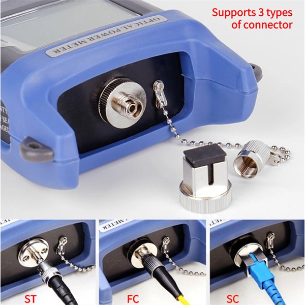
To use a power meter for fiber optic testing, always clean connectors first with lint-free wipes or click-to-clean tools. Select the correct wavelength and set your reference. You measure optical power in dBm or insertion loss in dB. Consistent procedures ensure accuracy. Verify light travels from. The most basic fiber optic measurement is optical power from the end of a fiber. This measurement is the basis for loss measurements as well as the power from a source or presented at a receiver. Typically both transmitters and receivers have receptacles for fiber optic connectors, so measuring the. An optical power meter measures the strength of light traveling through a fiber optic cable, giving you a reading in dBm (decibels relative to one milliwatt). This article will guide you through the methods, instruments, and key considerations for measuring fiber. Fiber optic cabling is the high-performance core of today's datacom networks. As network speeds and bandwidth demands increase, fiber performance requirements have become more stringent. Fiber testing is more important than ever. An OPM uses a photodiode to generate an electrical current proportional to optical power.
[PDF]

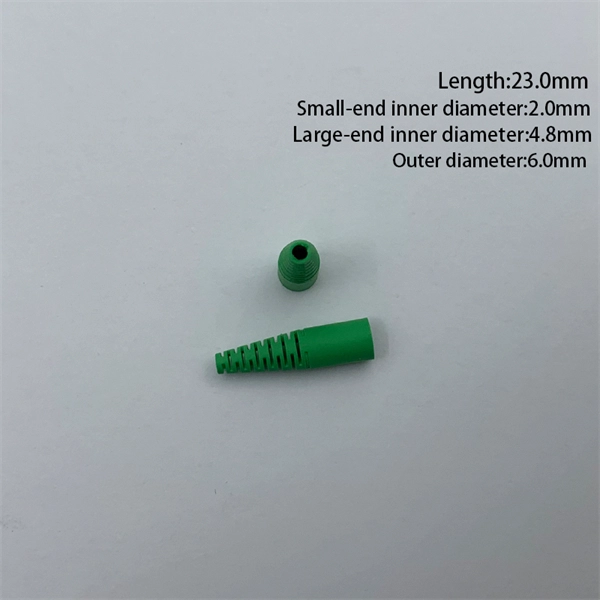
In this post, we'll walk you through practical tips, essential tools, common pitfalls, and the techniques that will help you get your fibre patch cable installations right the first time. Correct patch-cord installation is essential for maintaining low insertion loss, stable return loss, and long-term reliability in both indoor and outdoor fiber networks. Proper handling, routing, cleaning, bend-radius management, and connector alignment ensure that the optical link meets design. Proper connection of fiber optic cables is essential to harness these benefits fully, as even minor errors can lead to significant performance issues like signal loss. This guide addresses expert-certified best practices applied by professionals in the telecommunications, data. Yingda outlines the tools and materials needed to install fiber optic patch cords, as well as a complete step-by-step installation guide and important safety considerations to take. We will also tie this procedure back to the earlier discussion of multi-mode fiber types (OM1 to OM5) and connection. The Flex-Angle boot is designed to bend any angle or direction from straight to 90°. OMC flex angle boots for LC&SC fiber optic connectors are available on any single-mode or multimode patch cord. They are designed so the installer can pre-bend the boot into any direction or angle. Selecting the correct fibre patch lead is crucial for optimising signal performance and.
[PDF]

Indoor armored fiber optic cable are the latest networking infrastructure need. The cables provide ultimate mechanical protection, fire protection, and ease of installation, and thus they are suitable for indoor applications such as offices, data centers, and homes as well. These cables are suitable for both indoor and outdoor applications. Other specialized metal designs include square lock armored, spiral. In environments with high crush risk, rodents, or moisture, standard cables are not enough. What is an Armored Fiber Optic Cable? An. Supported applications include gigabit, 10 gigabit, and 40 gigabit Ethernet. Unsure Which Cables Will Suit Your Needs? What speeds and applications will this indoor armored tight-buffered plenum cable support? With bend-insensitive optical fibers (except OM1), this armored fiber optic cable is. These indoor fiber optic cables are used exclusively within buildings and must have a flame-retardant cable jacket to fit this purpose. Flame resistant cable may be deployed in-duct (conduit) or cable tray. Right selection of. Armored fiber cable is a fiber optic cable reinforced with additional protective layers to enhance its durability and resistance to external damage. These cables are designed to endure extreme environmental conditions, physical strain, and potential interference. The armor typically consists of.
[PDF]

This article provides a detailed technical comparison between fiber optic and copper cables, offering a clear perspective for engineers, network architects, and procurement managers. The core distinction between the two technologies lies in the physics of data. There are significant differences in performance between ADSS cables (all-dielectric self-supporting optical cables) and traditional optical cables, which are mainly reflected in the following aspects: 1. This type of fiber optic cable is designed to support its own weight without the need for additional support structures like messenger wires. The ADSS. There are several factors to assess when deciding which cable type is right for your application, including speed of connection for new customers, ease of changes and repairs, installer certification requirements, and the ability to expand the network over time. ADSS Fiber Optic Cables are a type of optical fiber cable designed specifically for. All-dielectric self-supporting (ADSS) cable is a type of optical fiber cable that is strong enough to support itself between structures without using conductive metal elements. It is used by electrical utility companies as a communications medium, installed along existing overhead transmission.
[PDF]

Fiber splitters serve as essential components in optical networks. These devices divide an optical signal from a single input into multiple outputs. This process enables efficient signal distribution across various network points. Fiber splitters function without the need for external. In the intricate web of modern fiber optic networks, where data travels at the speed of light across continents, fiber optic splitters play a silent yet pivotal role. These unassuming devices enable a single optical signal to be divided into multiple paths, making them indispensable for sharing. A fiber splitter, also known as a beam splitter, is a passive optical device that splits an optical signal into multiple signals. By dividing a single optical signal into multiple signals, fiber. Fiber optic splitters are vital in modern communication networks. Fiber optic splitters, such as plcsplitter and fbt splitters, are crucial in maintaining signal integrity, with considerations for IL (Insertion Loss) and RL (Return Loss). They are integral components in the world of telecommunication and data networking, crucial to maintaining reliable and efficient communication infrastructures. There are two primary.
[PDF]