
This is where a small but mighty hero comes into play: the Mode Conditioning Patch Cable (MCP). In this guide, we'll demystify what a mode conditioning patch cable is, why it's essential in specific network scenarios, and how it can save you from a world of connectivity headaches. This guide offers the key technical insights you need to select and install the optimal fiber optic cabling solutions for your specific needs. Covers the basics of fiber optic technology, including how light waves transmit data through thin strands of glass or plastic, and why fiber optics surpass. Fiber optic cables use light to transmit data, whereas traditional cables rely on electrical signals, which are more prone to interference and loss over distance. Connector types play a crucial. Fiber optic technology has transformed the way we transmit data, enabling faster, more reliable connections than traditional copper cables. Understanding fiber optic cable types is essential for anyone looking to build or maintain efficient fiber networks. We'll also. This is a plain-English guide for facilities and IT teams who want fiber that performs well, stays organized, and doesn't turn every add/change into a disruption. Start with the link's distance and speed, then pick single-mode (OS) or multimode (OM)—not the other way around.
[PDF]
Single fiber modules (BiDi) use one fiber for both transmitting and receiving data. This saves space and money. They are easier to set up and give steady communication. They use. There are two main types of fiber optic cables: single mode and multimode. Although they can do the same job in some instances, the different construction methods make each of them better suited to certain tasks and budgets. That makes picking between single mode and multimode fiber optic cables an. Single mode fiber optic cable is made up of a small diameter glass or plastic core surrounded by cladding, which is a layer of reflective material. This small diameter core, typically around 9 microns in diameter, allows only one mode of light to pass through, resulting in a narrower beam of light. The secret lies in fiber optic technology, and understanding the basics—1-core, 2-core, Single Mode (SM), and Multi-mode (MM)—is key to mastering this field. Let's break down these terms in simple, clear language with practical examples. Definitions · 1-core vs. multimode fiber in depth, explaining their structure, working principles, standards, and performance characteristics so that. Unlike copper cables, which rely on electrical signals, fiber optics use pulses of light to transmit data—offering unmatched bandwidth, low interference, and long-distance capabilities. But not all fiber cables are created equal: multimode (MM) and single mode (SM) fibers are the two primary types.
[PDF]

A typical fiber optic splice enclosure consists of several key components that work together to protect and organize the fiber splices. Standard enclosures contain: 1) Housing, 2) Cable fixation clamps, 3) Splice trays, 4) Sealing system. A splice box (also known as splice distributor) is a housing in which fiber optic cables begin or end. Fiber optics are fanned out in splice boxes that are situated at the end of fiber optic transmission paths. Optical cable joint box The optical cable joint box permanently connects two optical cables together and has a joint part for protecting components. The optical cable connection part, that is, the optical cable joint, is the part where the. An optical cable split fiber box, also known as a fiber distribution box or fiber optic splice closure, is a device used to terminate, splice, and distribute optical fibers. In this response, we will focus on the. This guide optimizes the original text by delving deeper into the three pillars of fiber network longevity: the impact of splicing technology, the strategic selection of splice boxes, and the essential maintenance protocols needed to ensure sustained, high-speed functionality. Fibre optic cables are manufactured in standardized lengths –.
[PDF]

At its core, a fiber termination box combines hardware and software components to facilitate fiber optic connections. The hardware includes protective enclosures, splice trays, adapters, connectors, and patch panels. A Fiber Terminal Box (FTB) is a customer-side termination and distribution device used at the end of the optical network. It is small, so it is considered a mini version of the optical distribution frame or optical distribution frame (ODF). The number of ports of fiber optic junction boxes ranges from 8. A fiber optic junction box, also known as a fiber optic distribution box or termination box, is a protective enclosure that facilitates the connection and management of fiber optic cables. It serves as a central point for organizing and distributing optical fibers, ensuring efficient connectivity. Fiber termination boxes are essential components in modern telecommunications infrastructure. They serve as the critical junction points where fiber optic cables connect, splice, and distribute data signals efficiently and securely. Here's a structured breakdown. This article provides an in-depth comparison of fiber terminal boxes and junction boxes to help clarify their differences and deepen your understanding.
[PDF]

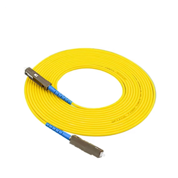
Multi-mode fiber optic patch cords utilize a larger core size, typically around 50-100 microns, allowing them to carry multiple modes of light. This design enables the transmission of data over relatively short distances with high bandwidth capabilities. A fiber-optic patch cord is a fiber-optic cable capped at each end with connectors that allow it to be rapidly and conveniently connected to telecommunication equipment. This is known as interconnect-style cabling. A fiber-optic patch cord is constructed from a core with a high refractive. These short fiber optic cords connect transceivers, switches, patch panels, and servers. Without them, even the best optical modules and switches cannot deliver performance. As data rates increase from 10G → 100G → 400G → 800G, patch cables must handle more bandwidth, more density, and stricter. Fiber optic patch cords, also known as fiber optic patch cables or fiber jumpers, are indispensable components in modern optical networks. They act as the critical link for interconnecting devices like optical switches, servers, and distribution frames. Understanding the various technical. Fiber patch cables, also called fiber-optic patch cords, are cables typically containing one or two optical fibers, which are equipped with standardized fiber connectors on both ends. The function of the fiber patch cord.
[PDF]

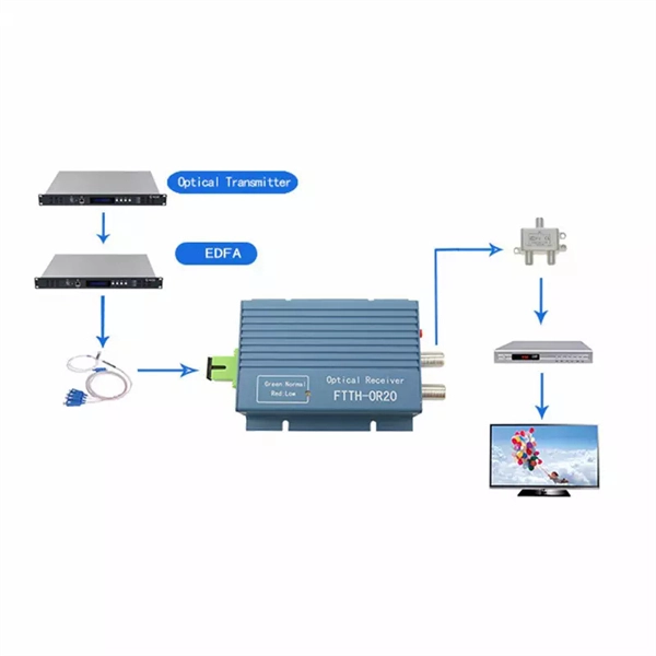
You can't directly connect a fiber optic cable to your router. You need an intermediary device. The key component is an Optical Network Terminal (ONT) or Optical Network Unit (ONU). Why Use Fiber Optic Internet? Before diving into the setup, let's quickly recap why fiber optics are worth the effort: Lightning-fast speeds (up to 1 Gbps or higher). Low latency for. The process to connect fiber optic cable to router requires careful attention to detail, but I'll walk you through every critical step with the precision and clarity you deserve. This comprehensive guide combines industry standards with field-tested practices to ensure you achieve a rock-solid. The fiber optic cable does not plug directly into a standard home router because the signal type must be translated. Our Experts are helping user's, who are facing issues with their tech gadgets like Router, Modem and extender. Here's a step-by-step guide to help you through it. Understand the Basics Before diving in, familiarize yourself with the components involved:. Connecting a fiber optic cable to a router involves a few key steps and specialized equipment. Check Your Fiber Optic Equipment Before you start, make sure you have the necessary equipment: Fiber Optic Modem (ONT – Optical Network Terminal):.
[PDF]
A fiber optic termination box is an enclosure designed to terminate incoming optical fiber cables and distribute optical signals to drop cables or patch cords. It integrates fiber splicing, adapter management, and cable protection in one compact unit. It is widely deployed in FTTH, FTTB, and other access networks to ensure stable signal transmission from backbone cables to end. ■ What is a Fiber Access Terminal (FAT)? A Fiber Access Terminal (FAT), also known as a Fiber Access Terminal Box (ATB) or Fiber Distribution Terminal (FDT), is a key component found in optimized fiber optic access networks for FTTH implementations. It acts like the "central nervous system". Fiber termination boxes play a vital role in ensuring efficient and reliable fiber management in FTTH applications. By understanding the components, types, and differences between various fiber management devices, businesses can make informed decisions when deploying and maintaining their fiber. But what exactly is the purpose of a fiber optic terminal box, and why is it so crucial in the realm of optical communication? First and foremost, a fiber optic terminal box serves as a robust protective shield for fiber optic cables and their delicate connections. It offers higher reliability and more flexible deployment and configuration than traditional terminal boxes. It is usually installed on the wall in the user's room or on the rack in the telecom room, and.
[PDF]

Configurations of 1x1 to n x m (e., 1x8 or 2x2) are available. The insertion loss of MM switches typically amounts to approximately 0. These switches can be delivered with any of the. Multimode fiber optic switches have emerged as a crucial component, enabling seamless connectivity and efficient data transmission. The MCSW Series Multicast Fiber Optical Switches enable simultaneous connection of one input to all outputs without loss. They support fully non-blocking, conflict-free switching of any number of optical inputs to any outputs, with complete configuration flexibility. The system is entirely passive. The Siemens Scalance X204-2 Multimode Switch requires a 24V UL Listed for Fire Application, Power Limited - Regulated Power Supply. Its Input Voltage is Regulated 24VDC and its Input Current is 265mA @ 24VDC. It is powered from the battery backed up local 24V power supply. Was this helpful? Does. For extremely precise measurement systems and sensor applications as well as for telecommunication applications LASER COMPONENTS offers fiber optical multimode (MM) switches with a fiber core diameter of 50 µm to 600 µm. There are switches are for all different kinds of requirements. Configurations. CONFIGURING THE SWITCH IN DESIGO CC/CERBERUS DMS. CYBERSECURITY DISCLAIMER.
[PDF]

Plug an SEL-2810 Fiber-Optic Transceiver With IRIG-B directly into a standard 9-pin serial connector (DB-9). No special mounting is required. The SEL-2810 receives power from the host device via the connector; no separate power supply or power wiring is needed. It also requires no. Improve safety, signal integrity, and reliability by using optical fiber instead of wire for instrumentation, protection, automation and other applications that benefit from economical fiber-optic links up to ½ kilometer long. Fiber-Optic Link— Establish EIA-232 communication between devices over a. The RLH Contact Closure Fiber optic converter transmits 8 digital input signals over fiber optic cable. Applications include alarm event triggering, building automation, environmental control systems, fire & alarm systems, gate control, traffic signal control equipment, and more. Use two optical fibers instead of 32 wires between outdoor or remote equipment and the control building to reduce costs, improve safety, and boost reliability. SFP transceivers bridge electrical and optical signals, making them indispensable in data centers, telecom networks, and.
[PDF]

Fiber splitters serve as essential components in optical networks. These devices divide an optical signal from a single input into multiple outputs. This process enables efficient signal distribution across various network points. Fiber splitters function without the need for external. In the intricate web of modern fiber optic networks, where data travels at the speed of light across continents, fiber optic splitters play a silent yet pivotal role. These unassuming devices enable a single optical signal to be divided into multiple paths, making them indispensable for sharing. A fiber splitter, also known as a beam splitter, is a passive optical device that splits an optical signal into multiple signals. By dividing a single optical signal into multiple signals, fiber. Fiber optic splitters are vital in modern communication networks. Fiber optic splitters, such as plcsplitter and fbt splitters, are crucial in maintaining signal integrity, with considerations for IL (Insertion Loss) and RL (Return Loss). They are integral components in the world of telecommunication and data networking, crucial to maintaining reliable and efficient communication infrastructures. There are two primary.
[PDF]
Find all you need for professionally buying wavelength division multiplexing devices: a comprehensive expert-curated directory of suppliers, scientific and technical background information, and an interactive AI-based tool with guidance for a structured decision process. A multiplexer is a digital device that combines several inputs into one line. The number of input lines to be multiplexed depends on the select lines' capacity. A mux makes it easier to convey data in systems that need multiple signals to be transmitted over a single medium. You appear to be visiting. We produce fiber-coupled Wavelength-Division Multiplexing (WDM) devices that combine (Mux) or separate (DeMux) multiple wavelength channels into or from a single optical fiber. Two types are available: integrated arrayed waveguide gratings (AWG), offering low cost, compact size, and precise ITU. WDM AWG CWDM4 module is based on silicon chip technology. It has compact, easy-to-assemble structure and good reliability. It can replace TFF (thin film filter) type CWDM. It is widely used in 40G and 100G high-speed active optical modules for optical signal Mux and Demux, such as QSFP+, QSFP28. wdm module is a truncation for Wavelength-Division Multiplexing, and is currently one of the most broadly involved innovation for high-limit optical correspondence systems. At the transmitter side, wdm module has numerous optical transmitters - each emanating at an alternate frequency -.
[PDF]

Over time, the constant expansion and contraction can make these cables brittle, increasing the risk of breakage, especially at joints and connectors. Ice accumulation is another significant concern in freezing weather. Fiber optic cables are the backbone of modern high-speed data transmission, offering unparalleled speed and reliability compared to traditional copper wires. Many advantages come with installing fiber optic cables over traditional copper cables, but that doesn't mean they are invincible. Fiber optic cabling problems with extreme cold happen when water finds its way into the ducts housing the cables. If water has the chance to enter into. Cold weather can affect fiber optic cables, but they are generally more resilient to temperature extremes compared to other types of cables, such as copper. Here's how cold weather can. For example, Bulgin's 4000 Series Fiber connector is the smallest sealed standard interface connector on the market. The fiber connection is UV resistant, salt spray resistant and sealed to IP66, IP68 and IP69K, while still providing an industry-standard LC interface as specified by IEC 61754-20. It's also widely utilized in telecommunications services, including the internet, television, and cellphones. Fiber optic internet connections are more popular globally because they provide various benefits over regular.
[PDF]
Nigerian mobile operators have deployed a total of 77, 235. 5km of fibre (On-land and Submarine) as at December 2022, according to a report by the Nigerian Communications Commission (NCC). According to NCC Nigerian Communications Commission said, with the continued deployment of the past few years, Nigeria's national optical fiber cable length is close to 40,000-kilometer, which greatly improve the quality of broadband Internet connections in the country. The report said that 49,367. 2km was deployed on land as terrestrial fibre optics cable, while 27,868. 3km was. Minister of Communications, Innovation and Digital Economy, Dr Bosun Tijani. The Federal Government is targeting the planned deployment of 90,000 kilometres of fiber-optic cable across Nigeria to start within the next six months. Project BRIDGE is the establishment of a Special Purpose Vehicle (SPV) aimed at deploying at least 90,000 km of Fiber Optic cables as Nigeria's core connectivity Infrastructure and national backbone for universal access to Information and Communication Technology (ICT) across Nigeria, under a. The Federal Government has announced an ambitious plan to lay 90,000 kilometres of fibre optic cable across Nigeria as part of efforts to deepen internet access and digital inclusion, a move it says is critical to delivering the dividends of democracy and boosting economic development. A critical component of the plan involves the establishment of a Special Purpose Vehicle (SPV).
[PDF]

This practical file details experiments conducted in Optical Fiber Communication, covering modulation techniques, system components, and performance analysis. An optical fiber is a glass or plastic fiber designed to guide light along its length, widely used in fiber-optic communication, which permits transmission over longer distances and at higher data rates than other forms of communications. Fiber-optic communication is a method of transmitting. Availability of plastic optical fiber (POF) The plastic optical fiber used in some of these experiments is available for science distributors. It is a 1000micron (1mm) POF available from several suppliers. FOA has samples available at no cost for teachers at schools in the US. Key experiments include amplitude modulation, frequency modulation, and pulse width modulation, aimed at understanding fiber optic systems. This document summarizes 10 experiments on optical fiber communication: 1. Studying a 650mm fiber optic analog link and the relationship between input and received signals. Optical fiber communication Laboratory Optical fiber communication Laboratory List of Experiments: 1. To set up a analog optical fiber link 2. To measure the characteristics of LED and LASER 5. Tech curriculum designed to provide a comprehensive understanding of optical fiber communication systems. This lab offers an immersive, web-based simulator that enables you to explore and experiment with key concepts in optical.
[PDF]

Here's a step-by-step guide to help you set up your fiber distribution box seamlessly: Before installing the fiber distribution box, ensure that your optical cables are properly prepared for connection. The optical fiber distribution box allows people to easily access the optical fibers in the box, and can well protect the optical fibers. In addition, the drawer structure also facilitates high-density wiring and good cable management. However, because optical fibers are fragile and can be easily. Keeping this page as a placeholder for now. Have any questions? Talk with us directly using LiveChat. Fix the rack to the ground with expansion bolts. Top installation: Dimensions of four connection holes on the top according to the. This instruction describes the installation of the Fiber Distribution Frame (FDF) manufactured by Corning Optical Communications. To order accessories that are purchased separately, contact Corning Optical Communications customer care for assistance. Read and understand this procedure (as well as. Optical fiber distribution frame is the wiring connection equipment between optical cable and optical communication equipment or between optical communication equipment. Distribution boxes are especially essential for FTTH networks, where they enable the efficient connection and management of optical fibers from a central.
[PDF]