Watch as we take you through the entire manufacturing process step by st. How to Make Electrical Pigtails: This is a basic tutorial on what electrical pigtails are and how to make them. Disclaimer: Always use multiple sources and do your homework before performing any electrical work. Also, make sure all work is done within national and local code. Combining is putting the layers of linerboard and medium together to form complete corrugated board. Medium is engineered to form easily into flutes as it is fed between two large gear-like rollers on the Wet End of the corrugator. Linerboard is engineered to remain flat as it adheres to the top. A corrugated box is a packaging carton made of a fluted (wavy) inner layer sandwiched between two flat sheets of paper. The thickness of the inner and outer sheets can be customized as per a brand's needs and the nature of the product. The three-layer structure creates a box that is both strong and. Pigtails act as bridges, allowing you to connect several wires to a single point without overloading connections. Professionals often prefer this method because it isolates issues, protecting downstream circuits from cascading failures. Why does this matter? Modern systems demand precision. A. The corrugated box manufacturing process involves several stages, beginning with paper rolls and ending with finished packaging boxes ready for shipment. These paper rolls are loaded onto the.
[PDF]

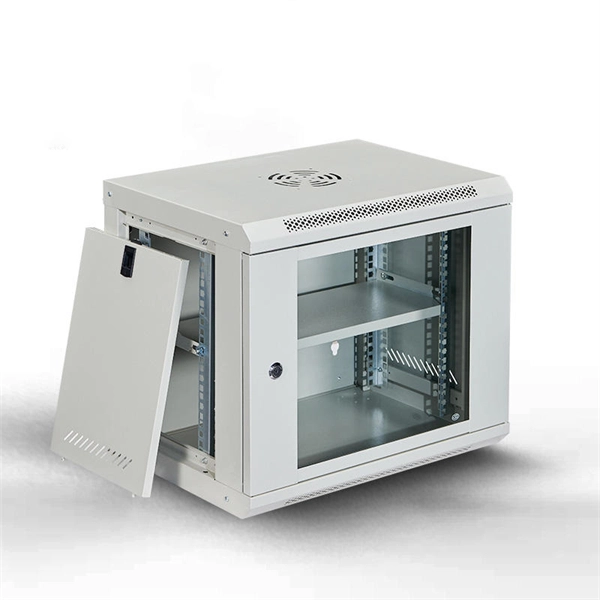
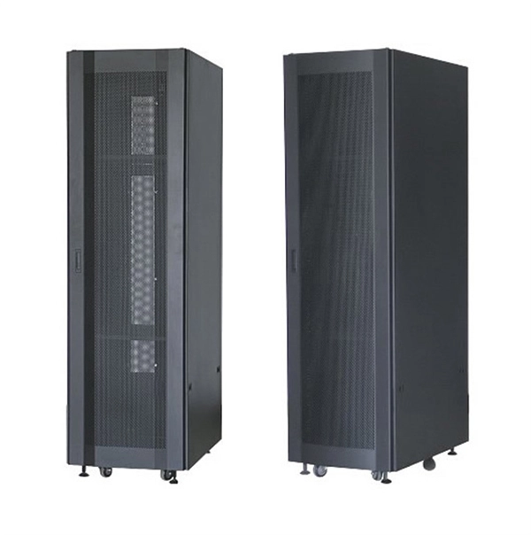
This complete guide explores everything you need to know about ODFs — from their structure, types, and key components, to installation best practices and modern design trends. Clients facing the exact demands of specialized environments—whether it's ultra-low-latency AI clusters, space-constrained military installations, or high-density telecom exchange points need more than off-the-shelf cabling. At FS, we place the customer at the heart of our operations. We are. This white paper provides a comprehensive guide to designing future-proof fiber optic networks, emphasizing a core-to-edge architectural approach. Key focus areas include backbone topologies, optical loss budgeting, standards compliance, and strategies for optimizing high-density environments like. In modern data centers and enterprise networks, Optical Distribution Frames (ODF) serve as the backbone for organizing, terminating, and managing fiber optic connections. As data centers, enterprises, telecom operators, and smart-building infrastructures deploy increasingly dense fiber links, ODFs provide the structured. Fiber optic network design refers to the specialized processes leading to a successful installation and operation of a fiber optic network. It includes first determining the type of communication system (s) which will be carried over the network, the geographic layout (premises, campus, outside.
[PDF]
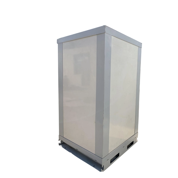
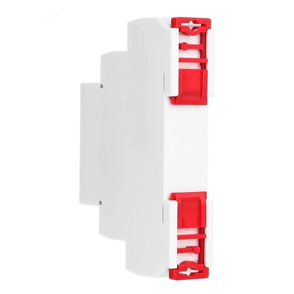
Whether upgrading an aging electrical panel or setting up your facility, this guide will walk you through the critical steps to installing an MCB Distribution Box safely. Strictly speaking, the word “Distribution Box (D-box)” can refer to two categories: electrical distribution boxes and septic tank distribution boxes. This article mainly talks about the first one. An electrical distribution box, also known as a power distribution box, panelboard, or consumer unit. These extras help make the box easier to install and maintain. Choosing the right distribution box isn't one-size-fits-all. You need to consider where it will be used, how much power it needs to handle, and how well it's built to last. Let's go through what matters most. Whether it is residential buildings, commercial facilities or industrial sites, the. This guide provides step-by-step instructions for connecting a distribution box and highlights key factors to consider during installation. It serves as a. Learn how to wire a distribution box step by step! This video shows real on-site footage of electrical installation, demonstrating safe and standardized wiring methods used by professionals.
[PDF]
In this guide, we'll walk you through the entire process of preparing fiber optic cable for splicing and termination to fiber connectors. We'll explore the necessary tools, safety precautions, and step-by-step procedures for cable connectors, mechanical and fusion. In this guide, you will find a chronological description of the fusion splicing process, the principal technical standards, and answers to the real-life questions network engineers and procurement teams may have. Therefore, we will also touch on cost factors, risk management, and best practices in. In this guide, we cover the basics of fiber optic splicing, how to perform splicing using two different methods, and finally some best practices to perform good fiber splicing. What is Fiber Optic Splicing and Why is it Needed? – #1. Two types of splices are used in fiber optic cabling one is Mechanical the other is Fusion. Before jumping into the physical steps, it's important to understand the two primary methods of fiber splicing: fusion splicing and. Learn how to splice fiber optic cable step by step in this complete guide! In this video, you'll see the full fiber splicing process — from fiber preparation, cleaving, and fusion splicing to final testing. For network managers and technicians, a poor splice can lead to significant signal degradation, network downtime, and costly troubleshooting.
[PDF]
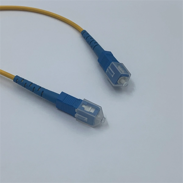
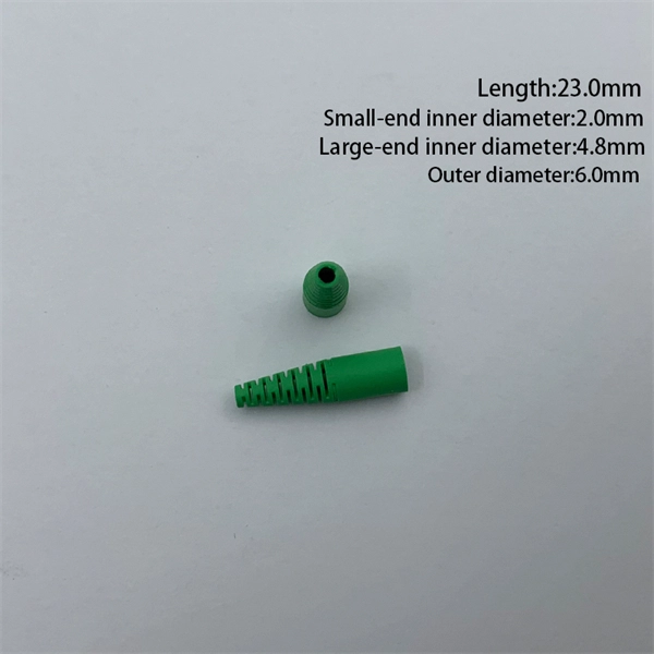
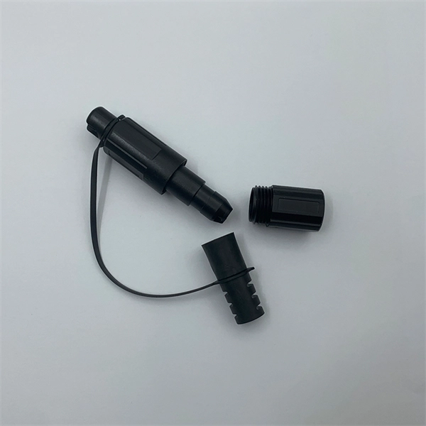
In fiber optics, pigtails are fusion-spliced to field fiber inside splice trays — the most common termination method in telecom and data center networks. In electrical work, pigtails connect multiple wires to a single device terminal. A pigtail is a coiled or looped section of tubing used in piping and instrumentation systems to absorb vibration, manage thermal expansion, and protect pressure instruments from direct exposure to process media. Moreover, its curved design allows it to flex under temperature or pressure changes. Pigtails play a crucial role in ensuring safe and efficient connections within electrical systems, especially when dealing with multiple wires or limited space. Understanding what a pigtail is and how it works can make your wiring projects smoother and safer. Whether you're replacing an outlet or. Whether you are a DIY or professional electrician, you will almost certainly use pigtail wires at some point in your project. This short-length wire creates something like a last mile (or last inch) connectivity to create continuity to the endpoint. And you only need a scrap wire to make this. Whether you're upgrading outlets or managing industrial circuits, these short connectors ensure power flows smoothly even when devices fail. Pigtails act as bridges, allowing you to connect. A pigtail connector is a short cable with a connector on one end and bare (stripped) wire or fiber on the other.
[PDF]
GYXTW is a fiber optic cable that can serve overhead, buried and through-tube scenarios according to line design requirements. This loose sleeve is filled with a. GYXTW form of fiber optic cable is one that has an outer tube structure laid in the air, most suitable for outdoor environments of overhead application. It conforms to the concept of design of central tube cable, which is also known as loose tube cable. Known for its durability and flexibility, this cable plays a critical role in both indoor and outdoor applications. This article explores the features, benefits, applications, and. GYXTW is a compact outdoor fiber optic cable design widely used in access and distribution networks, especially where space efficiency and mechanical reliability are required. GYXTW adopts a central loose tube structure, with optical fibers placed inside a gel-filled tube for moisture protection. GYXTW fiber optic cable is constructed by. This cable is used across different project and manufacturing stages — from network deployment to in-house cable production. Reliable finished cable supply for overhead network deployment, utility communication projects, and infrastructure integration. Used to supplement production capacity, expand. This specification covers the design requirements and performance standard for the supply of optical fiber cable.
[PDF]
All interval wiring should conform to the relevant International Best Practices. For general site work additional precautions are necessary. Other than supplies for welding purposes, cables carrying a voltage to earth in excess of 65V should have co. All interval wiring should conform to the relevant International Best Practices. For general site work additional precautions are necessary. Other than supplies for welding purposes, cables carrying a voltage to earth in excess of 65V should have continuous metal armour or sheath which has been effectively earthed. Where trailing cables are concern. An RCD or ELCB is to be installed to all final distribution boards and tested before use on each shift. To allow only the use of 110 volt for portable electric tools. Earth Leads Earth leads must be colored yellow and green, and yellow should be of stranded copper or copper alloy with a cross section of at least 6 sq.mm. The maximum size need not e. All extension cables / cords should have a current inspection tag affixed and should be checked for damage prior to use. Extension cables / cords in one office should not be used to supply power to another office, building or adjacent offices. Cables / Cords may not run through doors, windows or ceilings unless for the purposes of temporary constru.
[PDF]
Lighting Control System | Smart Lighting Wiring Setup | Full Guide In this video, you will learn how to connect and install a Lighting Control System step-by-step. This guide covers wiring setup, switch modules, dimming control, sensor setup and panel . as a guide for proper and reliable installation. The mounting location should e selected and prepared based on the application. All electrical wiring and mounting hardware (i. ) should be prepared with consideration of the requirements o cuit breaker before. Intelligent Lighting Controls' installation guides provide detailed instructions on how to install all of our solutions. The Lightolier Controls Optio Lighting Control Panels are high-performance, wall mounted lighting control panels which offer a wide range of dimming and relay modules to accommodate any lighting control application.
[PDF]
Fusion splicing is most widely used as it provides for the lowest loss and least reflectance, as well as providing the most reliable joint. Virtually all singlemode splices are fusion. 📦 For purchasing, use the RP Photonics Buyer's Guide for fiber cleavers. It provides an expert-curated supplier directory, buyer-focused technical background information, and structured selection criteria to support professional procurement decisions. In many applications of fiber optics, it is. The fiber optic quick connector/cold connector is a very innovative field-terminated connector, which contains factory-installed optical fiber, pre-polished ceramic ferrule and a mechanical splicing mechanism. The incoming optical fiber or indoor optical fiber can be inserted into the mechanical. A reliable fiber-optic network depends on more than selecting the right cable and connectors; it hinges on the quality of every splice. In fact the splice shall ensure high quality and stability of performance with time. Either joining method must have three primary characteristics. Fiber joints are the points where two optical fibers are permanently connected to create an uninterrupted transmission path. These connections are essential in fiber optic networks, enabling the extension, branching, or repair of fiber cables while ensuring minimal signal loss during transmission.
[PDF]
This video shows real on-site footage of electrical installation, demonstrating safe and standardized wiring methods used by professionals. What is the Price of Electrical Distribution Boxes? What are the common sizes for Distribution Boxes? How to Estimate the Size of the Box that I Want? Can I Customize a Distribution Box? How to Choose a Suitable Electrical Distribution Box? How does a Distribution Box Work? What's the Difference. In modern electrical systems, cable distribution boxes (also known as electrical distribution boxes or distribution boxes) play a crucial role as the key hub for managing, distributing, and protecting circuits. Whether it is residential buildings, commercial facilities or industrial sites, the. Ensure safe placement: install in dry, accessible areas with good ventilation and at appropriate height (typically ~1. Practice good wiring: secure grounding, neat cable management, proper insulation, and correct wire gauge and breaker size. Include protection devices like breakers, fuses, and. Plan of electrical installations for a shopping center; electrical installation; lightning; power outlets; single-line diagrams and load chart; typical details. It discusses key considerations for wiring types, circuit diagrams, load estimations, and costing. The main sections cover electrical service and supply, internal distribution, residential distribution.
[PDF]
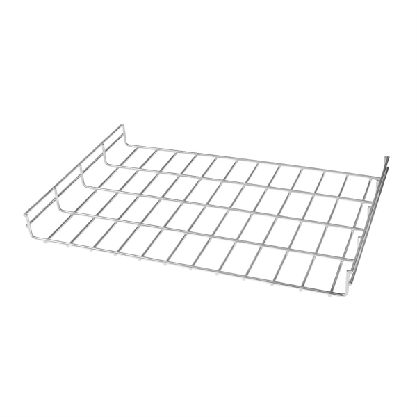
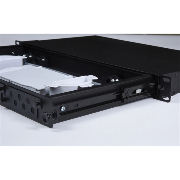
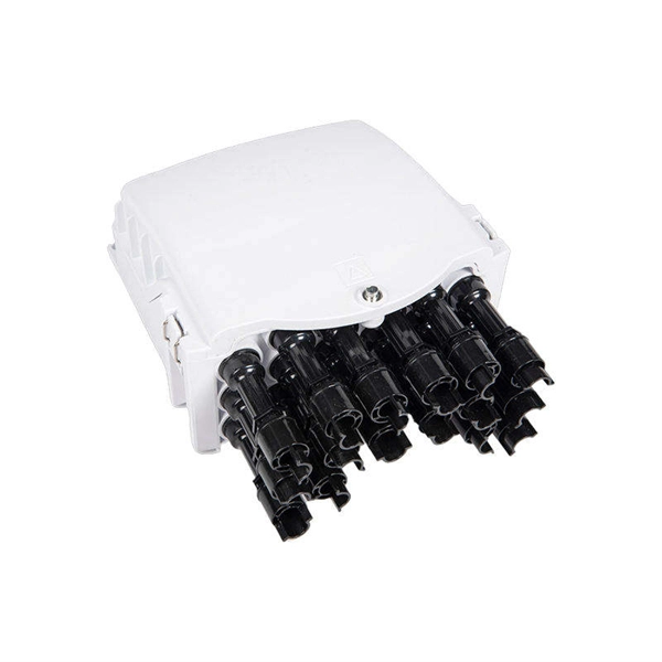
When selecting the right fiber optic splice tray, prioritize compatibility with your cable type, secure fiber management, and ease of installation. Corning splice trays offer an easy way to store fiber optic cables and splices while protecting them from damage during fusion and mechanical splicing. The trays are engineered to use with both loose tube and tight-buffered optical cables. Their generous size and craft-friendly design help prevent. Fibre optic splicing trays are an essential part of manipulating and ordering optical fibers inside a network structure. Since the need for higher data rates and effective communication gets more robust, the utilization of optical fibers has become increasingly widespread across multiple spheres of. Optical / fiber optic 12 or 24 fiber splice tray for holding spliced fibers of fiber optic cable. For most network installations—especially in data centers or FTTH (Fiber-to-the-Home) deployments—a modular, stackable splice tray with 12 to 24 port. Discover CommScope fiber splice trays, fiber optic splice trays, and a convenient fiber splice organizer. Organize fiber connections with ease. Because optical fibers are sensitive to pulling, bending, and crushing forces, use fiber splice trays to provide secure routing and an easy-to-manage environment for fragile fiber splices. In the past, fiber optic splice trays were usually installed in a box that hung on the wall.
[PDF]
Discover a wide selection of high-quality Busbar in Congo from trusted suppliers. These busbar punching shear line available on Alibaba. com are ideal for bending metal alloys. CONGO CABLES & TRANSFORMERS SAS was established in early 2022 with an objective to provide complete power solution that includes Copper Rods, Copper hanger bar, Copper Billets, Copper wires and cables, Copper and aluminum conductors, Transformers etc. produced in the state-of-the art manufacturing. This CNC busbar shearing and punching machine is to cut/punch (of round/square/special holes and slot types)/chamfer/emboss the copper/aluminum busbar etc. Flexible Class-5 Copper Conductor as per sans 1411-1 BS 6360 05ºC to 70ºC. Minimum Bending Redius Wire Outer Dia 5x Wire Outer Dia No.
[PDF]
Supported by air within insulated pillars, the busbar collects incoming electricity and conducts it for distribution to outgoing feeders. They are typically made from solid or hollow conductive metals, such as copper, aluminum, or brass. In electric power distribution, a busbar (also bus bar) is a metallic strip or bar, typically housed inside switchgear, panel boards, and busway enclosures for local high current power distribution, transmission, or switching substations. Its primary role is to carry large current loads and connect multiple circuits together. Think. A bus bar offers a low electrically resistant path to incoming or outgoing currents. Find out more about them in this article. What is a bus bar? An electrical bus bar is a solid-state conductor made from copper and aluminum- present in the industry for over 150 years. It carries higher amount of currents in a limited space and to which all the incoming and outgoing feeders are connected in a substation.
[PDF]
In , a busbar (also bus bar) is a metallic strip or bar, typically housed inside,, and for local high current power distribution, transmission, or switching substations. They are also used to connect high voltage equipment at electrical switchyards, and low-voltage equipment in. They are generally uninsulated, and have sufficient stiffness to be s.
[PDF]

This comprehensive guide explores the technical requirements, installation best practices, and protection coordination strategies for MCCB-busbar connections. Messy distribution boxes are dangerous and very hard to fix. This guide shows you how to organize circuit breaker wiring properly. You will learn to build a safe, efficient, and professional electrical system today. Circuit breaker wiring configurations involve organizing main switches, busbars. An electrical panel box, also known as a breaker box or a distribution board, is a crucial component of any electrical system. It serves as a central hub for distributing electricity throughout a building, ensuring that power is delivered safely and efficiently to all the required locations. The distinction between 1P and 2P circuit breakers plays a pivotal role in determining the appropriate protection level for various circuits. Wiring Square D Panel refers to the process of connecting electrical circuits within a Square D panel, which is a type of electrical panel commonly used in residential and commercial buildings. The electrical panel, also known as a distribution board or breaker box, is responsible for distributing. While some homeowners may attempt this, it's highly recommended to hire a qualified, licensed electrician for circuit breaker box wiring. This is a complex and potentially dangerous task that involves working with high voltage electricity. To understand how a breaker box works, it is helpful to.
[PDF]