Mouser offers inventory, pricing, & datasheets for Bulk Transimpedance Amplifiers. The Relevance Inspector will open in the Coveo Administration Console. Transimpedance amplifiers parameters, data sheets, and design resources. Pricing (USD) Filter the results in the table by unit price based on your quantity. An instrumentation amplifier is a precision differential amplifier, typically built from three op amps, designed for accurate measurement of very small voltage differences in noisy environments. How it works: Two input buffers and a difference amplifier provide high input impedance and excellent. 1,Who we are ? Our headquarters is located in Shenzhen China with marketing experiences more than 16 years, The company has a professional R & D team, sales, procurement, logistics, warehousing, solutions, after-sales, to provide one-stop component services, in the field of industrial drones. Marvell's transimpedance amplifier (TIA) portfolio powers PAM4 and Coherent-based pluggable optical modules for high-speed cloud AI connectivity and long-haul optical links from 100G to 1. More data per optical symbol compared to older technologies Powering the fastest networks on. High-performance TIAs for next-generation optical receivers. Coherent's portfolio of high-speed transimpedance amplifiers (TIAs) delivers best-in-class signal integrity, high programmable gain, and exceptional power efficiency for optical interconnects ranging from 56Gbps to 224Gbps per channel.
[PDF]
In, a transimpedance amplifier (TIA) is a to converter, almost exclusively implemented with one or more (opamps). The TIA can be used to amplify the current output of, photo multiplier tubes,, and other (that are modeled well as a ) into a usable voltage.
[PDF]

This guide aims to provide a concise understanding of multimode fiber optic cable and its applications. We will explore its characteristics, advantages, specifications, and real-world uses. Multimode fiber (MMF) is an optical fiber designed to carry multiple light propagation paths—or modes—simultaneously. This is made possible by its relatively large core diameter, typically 50 or 62. 5 microns, compared to the ~9-micron core in single-mode fiber. The wider core accepts light from. Multimode fiber optic cables are essential in modern data communication systems since they can transmit data efficiently and at high speeds over short and medium distances. We will explore its. They consist of a transmitter on one end of a fiber and a receiver on the other end. Most systems operate by transmitting in one direction on one fiber and in the reverse direction on another fiber for full duplex operation. Most systems use a "transceiver" which includes both transmission and. Multi-mode optical fiber is a type of optical fiber mostly used for communication over short distances, such as within a building or on a campus. Multi-mode links can be used for data rates up to 800 Gbit/s.
[PDF]

Optical modules convert electrical signals into light to move data quickly and reliably in AI systems, enabling fast and smooth data processing. Using advanced optical modules boosts AI system speed and bandwidth, helping handle large data loads with low delay and high efficiency. Optical modules. Laboratory utilities: framework for communication with laboratory equipment and post-processing of data (opticomlib. You can install opticomlib using pip: or from source code: NumPy Compatibility: binary_sequence and electrical_signal now fully support NumPy protocols, allowing direct use with. The optical module serves as a crucial component in optical fiber communication systems, operating at the physical layer, which is the lowest layer in the OSI model. Its primary function is to achieve optoelectronic conversion by converting electrical signals into optical signals and vice versa. An. Learn about the components inside a coherent optical engine, what they do, and how they use modulation to send and receive data. Optical communications over metro, long-haul, and submarine networks once used simple direct-detect technology. That's no longer the case.
[PDF]

Cable Trays* — Max two 24 in. (610 mm) wide by max 6 in. (151 mm) deep open-ladder cable tray with channel-shaped side rails formed of 0. 54 mm) thick aluminum or min 0. In practice, cable tray dimensions are a system of interrelated measurements —width, depth, length, and material thickness—that directly affect cable fill compliance, heat dissipation, structural loading, and long-term expandability. From an engineering standpoint, cable tray dimensions are not. Perforated Cable Tray System expertly constructed from high-grade stainless steel, offering exceptional durability and resistance to corrosion. With side height 100mm. A properly designed and installed cable tray system will provide. Studs — Wall framing to consist of wood studs or channel shaped steel studs. Wood studs to consist of nom 2 by 4 in. Additional studs shall be used to completely frame. Best Size: Here, deep trays (75mm to 150mm) are used since power cables are typically thick and heavy. Data cables, such as your Wi-Fi or computer ones, are extremely sensitive. They do not get hot; however, they do not like to hang or sag. In case a data cable folds in an excessive manner, the. ect the minimum bend ra-dius for cables as they exit the bottom of the cable tray. A rung spacing of 6 to 9 inches (150 to 230 mm) is preferable when the cable tray cont d for instrumentation and control applications that require additional protec eferred to support and protect numerous small.
[PDF]

A ladder type cable tray tee is a fitting used to create a branch in a cable tray system, allowing cables to be routed in three directions. Its "T" shape provides a secure and efficient way to split cables from a main tray into two separate paths, ensuring organized and flexible. A cable tray tee and tee cover are components used in cable management systems to support and protect electrical and data cables. Here's a brief explanation of each:. Rigid steel cable tray tee fitting with zero tangent, safety bottom, and full accessory support. ventilation to heat producing cable such as power communication and other with the same or different width of the cable run. All fittings are available in sizes and types corresponding to the straight cable tray sections. These fitting are including: elbow, horizontal cross, vertical inside. NOTE : Equal or un equal tees can be supplied. When ordering state widths W1xW2xW3.. Office: 147/22 Nguyen Sy Sach Street, 15 Ward, Tân Binh Dist, HCMC,VN. Is it possible to connect 2 cabletrays with a "branch piece (left picture)" instead of a "tee (right picture)". The tee has 3 connectors, the branch piece only has 1 connector. I would like to ajust the "Type properties -> Fittings -> Tee" with the branch family, but can't get it accomplished.
[PDF]

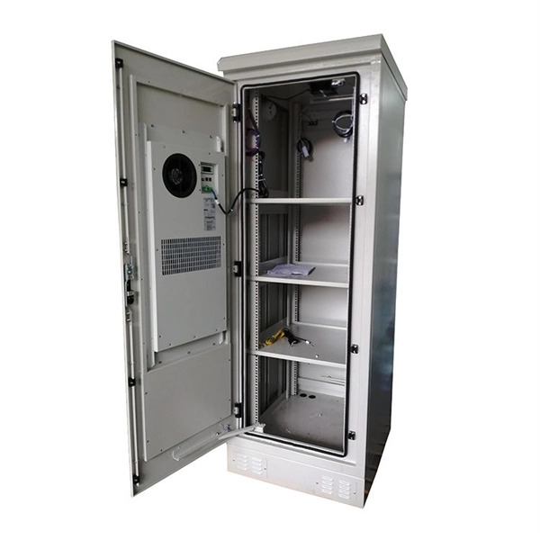
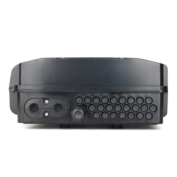
In modern FTTH architectures, the ODN is the physical fiber layer that distributes optical signals from the central office to end users. Operators consider ODN design as one of the most important factors affecting: Network coverage Optical loss performance Deployment cost. This passive layer is known as the Optical Distribution Network (ODN). Its role is to provide an optical transmission channel between the OLT and the ONU. The ODN network design is a physical facility that connects the communication room and user equipment, and is a key component. Short summary: The Optical Distribution Network (ODN) is the passive infrastructure linking the central office to the subscriber in FTTH. This guide delves into essential ODN components like splitters, distribution boxes, and ODFs, showcasing how Hainan ZTO Cable Co. It's the silent, robust highway that delivers blazing-fast Fiber-to-the-Home (FTTH) and 5G services. The maximum permissible optical power attenuation between OLT optical ports to ONT input is 28dB, which is by utilizing the so-called Class B optical network. At the heart of every Fiber-to-the-Home (FTTH) deployment lies the Optical Distribution Network (ODN) — a meticulously engineered passive infrastructure that enables operators to deliver massive bandwidth, low latency, and reliable service to millions of users. The ODN connects the Optical Line.
[PDF]
The system in this example contains the following elements: 1. 2 Pseudo-random Bit Stream (PRBS) block 2. 2 NRZ Pulse Generator (NRZ) 3. 1 CW Laser (CWL) 4. 3 1x2 Fork (FORK) 5. 2 Electrical Not Gate (N.
[PDF]
Use this Raman amplifiers buying guide to compare major types, define selection criteria, and find suppliers: Professional purchasing of high-value photonics products is a substantial responsibility, where a structured decision-making process is essential. RP Photonics offers a lot of help: Get. The D7000 PDRA5014 is a high-power, low-noise raman fiber amplifier designed for distributed raman amplification, offering cost-effective solutions to extend the optical link power budget and significantly enhance OSNR. The PL-1000R enables long distance DWDM solutions and facilitates the transport of 100G/200G/400G and 800G wavelengths over. Our Raman amplifiers leverage internally developed, state-of-the-art 14xx pump lasers, internally developed intelligent algorithms for autonomous gain control, and robust safety features to deliver network-ready solutions. Key points of differentiation include market-leading metrics on power. Beautiful Complete Kaiser Optical Raman RXN2 Spectrometer Spectroscopy System! Get the best deals for Raman at eBay. We have a great online selection at the lowest prices with Fast & Free shipping on many items!. This guide addresses the technical and procurement needs of professionals seeking reliable Raman fiber amplifiers for long-haul optical transmission systems. Based on analysis of six leading suppliers from China—including Hangzhou Fullwell, Ningbo Youxin, Wentop Tech, Shenzhen Uonel, Xiamen.
[PDF]
Raman amplification is a way of increasing the signal strength in an optical fiber. It is often used in a. For submarine applications, Raman amplification minimizes the number of underwater repeaters, enhancing reliability and cost-efficiency, while in terrestrial setups, it facilitates ultra-long-haul links over thousands of kms with reduced infrastructure needs.Further reading• Poem, Eilon; Golenchenko, Artem; Davidson, Omri; Arenfrid, Or; Finkelstein, Ran; Firstenberg, Ofer (26 October 2020). • •.
[PDF]
There are several different physical mechanisms that can be used to amplify a light signal, which correspond to the major types of optical amplifiers. In doped fiber amplifiers and bulk lasers, stimulated emission in the amplifier's gain medium causes amplification of incoming light.OverviewAn optical amplifier is a device that amplifies an directly, without the need to first convert it to an electrical signal. An optical amplifier may be thought of as a without an, or one in which. The principle of optical amplification was invented by on November 13, 1957. He filed US Patent US80453959A on April 6, 1959, titled "Light Amplifiers Employing Collisions to Produce Population Inversions".
[PDF]
For submarine applications, Raman amplification minimizes the number of underwater repeaters, enhancing reliability and cost-efficiency, while in terrestrial setups, it facilitates ultra-long-haul links over thousands of kms with reduced infrastructure needs.OverviewRaman amplification is a way of increasing the signal strength in an optical fiber. It is often used in a fiber that carries a signal for a long distance (such as in an undersea cable). Technically, it works by stimulating. • Poem, Eilon; Golenchenko, Artem; Davidson, Omri; Arenfrid, Or; Finkelstein, Ran; Firstenberg, Ofer (26 October 2020). • •.
[PDF]