
This AutoCAD DWG file includes a complete Single Line Diagram (SLD) of a Distribution Board, showing circuit breakers, wiring connections, and load distribution for lighting, power, and mechanical systems. Knowledge of the basic electrical power distribution system and its components will help the operator understand the importance of electrical power distribution systems. Failure-free power e. Overlapping protective zones a. Protective relays A single, or one-line. A power distribution box (also called PDU or distro) directs electricity from a main source to multiple circuits. It acts like a hub or traffic controller, managing power flow to different areas or devices. Key components include circuit breakers, fuses, bus bars, and internal wiring for safety and. Check electrical parameters: First understand the basic electrical parameters of Distribution box so that you can have a general understanding of the capacity and performance of the distribution box. Analyze the incoming line part: Determine the incoming line source of the distribution box and. ndards and conformity assessment activities in the United States. ANSI facilitates and promotes voluntary consensus standar rty or economic loss due to fire, electrical and related hazards. Now, let's look at how consumers use electrical power. What is a Electrical Power Distribution System? 1. Power supply is received from LT panel and distributed to the outgoing feeders for utilization.
[PDF]

Distribution box The system diagram usually shows the electrical connection and configuration inside the distribution box in a graphical way, including busbars, circuit breakers, fuses, load devices and other elements. In practical applications, the corresponding system diagram can be drawn. A wiring diagram symbols chart is a visual representation of the various symbols used in electrical diagrams. It provides a quick and easy reference guide to understanding the meaning behind each symbol. These symbols can represent different electrical components, such as switches, resistors. Hey, in this article we are going to see the Single Phase Distribution Box Wiring Diagram and Connection Procedure. A distribution board or distribution box is where the main power supply is distributed to multiple loads. Understand its role in electrical systems and safety. It helps control and distribute electricity to different areas. Inside. In the world of electrical installations, the term DB box —short for Distribution Board box —refers to the central unit that distributes incoming electrical power to multiple outgoing circuits in a building. Whether you're powering up a residential home, a commercial office, or an industrial plant. Power distribution panel is used for utilization of equipment. A molded case circuit breaker are used which incomer supply is connected with LT panel and outgoing supply is connected width panel busbar.
[PDF]

In this guide, you will learn how to interpret network diagrams like a pro, from symbols and scope to segmentation, dependencies, troubleshooting, and security clues. A rack elevation diagram is a visual representation of the equipment and components contained within a rack in a data center or server room. It provides a clear overview of the physical layout of the rack, including the placement and positioning of servers, switches, storage devices, and other. Learn how to read and interpret network diagrams effectively to troubleshoot, validate security, and plan network changes with confidence. Have you ever opened a network diagram and felt like you were staring at a subway map with no station names? That is a common problem, even for experienced IT. Network cabinet cabling describes the structured connection and arrangement of all IT components in a server rack. The aim is a secure, maintainable and scalable operation of the network environment. The amount. A standard operating procedure, or SOP, is a set of step-by-step instructions compiled by an organization to help workers carry out complex routine operations. Work instructions should be very detailed on "how" to accomplish a specific job, task or assignment. It helps teams understand network architecture, data flow, and dependencies, making it easier to design infrastructure, troubleshoot issues, and plan.
[PDF]

This guide breaks down everything you need to know about electrical distribution boxes in plain English. We'll explain what they are, the different panel types you'll encounter, NEC 408 requirements that govern their installation, and common applications for each type. The power distribution boxes deliver electricity from the main electrical main to other circuits. Several distribution boxes are designed for specific use in offices or industries. Main Distribution Board (MDB) 2. Each. Distribution boxes, also known as electrical distribution boards or panels, are pivotal components in electrical systems, ensuring the safe and organized distribution of electrical power throughout residential, commercial, and industrial environments. It receives power from the main electrical supply and divides it into separate circuits, each. Electrical control panels and distribution boxes are the backbone of modern electrical systems. From powering homes and industrial facilities to supporting medium-voltage infrastructure, these enclosures ensure safe, efficient, and reliable power distribution. Whether it's a small electrical.
[PDF]
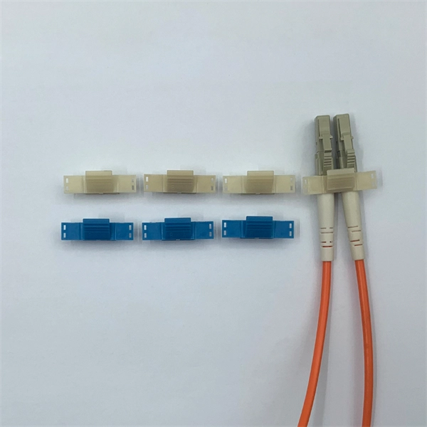
The 8 Port Fiber Access Terminal (FAT) is designed to connect feeder cables to subscriber drop cables for FTTH last-mile fiber connectivity; it can achieve direct or branch and terminal connection in FTTH or FTTB projects. FTB-SC8-WOPA type fiber optic terminal box is designed for FTTx application, which is cable to meet at least 8 users requirements. It can help splicing, splitting, storage and management with suitable space. Simple with light weight in design, special snap clip close system coinvent for user. ORCA® terminal optic box it is the best solution for indoor optical cable distribution or termination. The plastic case it is very light for a simple use. The FOTB fit the SC Simplex adapter (on request with ST and FC adapter). It is possible to buy the unloaded version (w/o Adapter) or the. Maximum capacity: 8 SC simplex, 8 LC duplex. The 8 port Fiber Distribution Box is sturdy in structure, lightweight in size, and easy to install. Built with high-density configurations and rugged materials, this MST box is perfect for installations in harsh environments like 4G/5G. The wall-mounted optic fibre termination box allows for easy organization of optic fibre cables (up to 4 fibres, depending on the installed adapters.
[PDF]

The 6 terminal junction box wiring diagram provides a visual representation of how the various wires and connections should be made within the box. It shows the layout and arrangement of the terminals, as well as the color coding and labeling of the wires. Hey, in this article we are going to see the Single Phase Distribution Box Wiring Diagram and Connection Procedure. A distribution board or distribution box is where the main power supply is distributed to multiple loads. It provides a quick and easy reference guide to understanding the meaning behind each symbol. These symbols can represent different electrical components, such as switches, resistors. This technical article aims to take you on a journey through the fundamental terminals and other connecting elements of wiring diagrams and electrical schematics and to delve into the minute intricacies of the components that form them. From the familiar male and female terminals that form the. An electrical panel box, also known as a breaker box or a distribution board, is a crucial component of any electrical system. Whether you're an electrician or a DIY enthusiast, this guide will help you understand the basics of home electrical distribution. more Welcome to our. The Engineering Base terminal block diagram is a special template showing information about terminal blocks, terminals and their accessories. There are two methods for creating a terminal block.
[PDF]

This guide covers the essential tools and step-by-step procedures for low-loss fiber optic cable repair. Understanding the causes and types of fiber optic cable damage helps detect issues early and determine when repair is needed. Construction Activities: Accidental damage during construction. Step1 : Identify the optical cabinet and network operating center, and find the fiber optic splitter. Step 2: Identify the splitter number. Step 4: Find the optical fiber port and cable sequence that leads to the user. 2) The. This complete guide covers everything from identifying causes of failure to advanced repair techniques, drawing on the latest industry standards and innovations. Whether you're a network technician, IT professional, or telecom operator, you'll find practical steps, tools, and tips to restore. If you accidentally break a fiber optic patch cord in your server room or in any of your switch gear, now you can repair it on the spot and get back up and running in minutes. Adhering to precise methodologies, we can mend impaired cables. By understanding these key elements and following the outlined steps, you can effectively repair fiber optic cables and maintain the high-performance network necessary for today's demanding communication needs. When it comes to ensuring nice network experiences for users, the condition of a fiber.
[PDF]

Plug an SEL-2810 Fiber-Optic Transceiver With IRIG-B directly into a standard 9-pin serial connector (DB-9). No special mounting is required. The SEL-2810 receives power from the host device via the connector; no separate power supply or power wiring is needed. It also requires no. Improve safety, signal integrity, and reliability by using optical fiber instead of wire for instrumentation, protection, automation and other applications that benefit from economical fiber-optic links up to ½ kilometer long. Fiber-Optic Link— Establish EIA-232 communication between devices over a. The RLH Contact Closure Fiber optic converter transmits 8 digital input signals over fiber optic cable. Applications include alarm event triggering, building automation, environmental control systems, fire & alarm systems, gate control, traffic signal control equipment, and more. Use two optical fibers instead of 32 wires between outdoor or remote equipment and the control building to reduce costs, improve safety, and boost reliability. SFP transceivers bridge electrical and optical signals, making them indispensable in data centers, telecom networks, and.
[PDF]

Numerical relay are embedded with specialized digital signal processor (DSP) as the computational hardware. By using DSP as the relay's processor, the relay is capable of meeting the fundamental protective requirements such as reliability, sensitivity, selectivity and speed . Thus, various protective devices are used to protect the power system, of which digital signal processor (DSP) numerical relays are capable of significantly improve protection operations. Therefore. Manuals and User Guides for Samwha DSP DSP-VIP-PM Motor Protection. We have 1 Samwha DSP DSP-VIP-PM Motor Protection manual available for free PDF download: Manual Samwha dsp DSP-VIP-PM Motor Protection Pdf User Manuals. View online or download Samwha dsp DSP-VIP-PM Motor Protection Manual. Many of the new protection relays are microprocessor based and are generally referred to as numerical relays. This means that signals from transducers are sampled at fixed time intervals, digitally encoded, and processed by equipment which resembles a computer to derive relaying information, e.
[PDF]
In electric power systems and industrial automation, ANSI Device Numbers can be used to identify equipment and devices in a system such as relays, circuit breakers, or instruments. The device numbers are enumerated in ANSI/IEEE Standard C37.2 Standard for Electrical Power System Device Function Numbers, Acronyms, and Contact Designations. Many of these devices protect electrical. List of device numbers and acronyms• 1 - Master Element• 2 - Time-delay Starting or Closing Relay• 3 - Checking or Interlocking Relay, complete Sequence• 4 - Master Protective. A suffix letter or number may be used with the device number; for example, suffix N is used if the device is connected to a Neutral wire (example: 59N in a relay is used for protection against Neutral Displacement); and suffixe.
[PDF]
Distance relays, also known as impedance relay, differ in principle from other forms of protection in that their performance is not governed by the magnitude of the current or voltage in the protected circuit but rather on the ratio of these two quantities.OverviewIn, a protective relay is a device designed to trip a when a is detected. The first protective relays were electromagnetic devices, relying on coils operating on moving par. Electromechanical protective relays operate by either, or. Unlike switching type electromechanical with fixed and usually ill-defined operating voltage thresholds.
[PDF]
Thermal relays are the perfect solution for providing protection to motors which provides the most precise tripping for the electric motor during single phasing and overload. This article discusses an overview.
[PDF]

This article describes the anti-pumping relay, its definition, function, and circuit diagram. In a circuit breaker it is desired that when close and trip operation is performed on the circuit breaker with the closing coil energized, the subsequent closing operation should be prevented. So let's. Anti-Pumping relay is nothing but a NO contact, which means when the circuit breaker in closed condition the relay will be as NO point and if the circuit breaker in open condition the relay will be as NC Condition. The anti-pumping relays is connected in series with the circuit. An anti pumping relay (also called antipumping relay or Y-relay and ANSI 94 Trip or Trip-Free Relay) is a protective device that prevents a circuit breaker from closing repeatedly when a continuous close command is present. In simple terms, it stops your circuit breaker from “pumping” – which means. Anti-pumping relays are used in circuit breakers to prevent the breaker from closing unexpectedly after tripping. If the TNC switch fails (Trip normal close) or there is any problem with the CB (circuit breakers) closing circuit, the continuous CB (circuit breakers) close command can be extended to. Why is the Anti-Pumping Relay Used? A circuit breaker is a very important equipment for a high-voltage power system. It protects the system from high current or voltage during a faulty condition.
[PDF]

This guide provides clear cost ranges in USD and practical pricing details for U. Typical cost range for a single relay is $2–$150 depending on type and rating. Buyers typically pay a range for relays, and cost is driven by relay type, coil voltage, contact rating, and packaging. This guide presents practical price estimates in USD, with low–average–high ranges and real-world factors that affect total cost. Assumptions: region, specs, labor hours. Relays. The SEL-351 Protection System has built-in Ethernet and IEEE C37. 118 synchrophasors, and is ideal for directional overcurrent applications. Optional Mirrored Bits communications and power quality monitoring add flexibility to solutions. The SEL-351 is the protection standard for utility and. Buyers typically pay a modest amount for small signal relays and higher sums for industrial or specialty units. The main cost drivers are the relay category (signal, automotive, or industrial), quantity, and installation requirements. Although failure of a protective relay system may have severe local or regional impacts, most protective relay systems are not required to operate to prove they are in working order. Ensuring that. What are Protection Relays and How Do They Work? Protection relays are specialized devices designed to detect abnormal conditions in electrical systems and initiate appropriate actions to protect equipment and personnel. These intelligent sentinels continuously monitor electrical parameters and.
[PDF]
In electric power systems and industrial automation, ANSI Device Numbers can be used to identify equipment and devices in a system such as relays, circuit breakers, or instruments. The device numbers are enumerated in ANSI/IEEE Standard C37.2 Standard for Electrical Power System Device Function Numbers, Acronyms, and Contact Designations. Many of these devices protect electrical. List of device numbers and acronyms• 1 - Master Element• 2 - Time-delay Starting or Closing Relay• 3 - Checking or Interlocking Relay, complete Sequence• 4 - Master Protective. A suffix letter or number may be used with the device number; for example, suffix N is used if the device is connected to a Neutral wire (example: 59N in a relay is used for protection against Neutral Displacement); and suffixe.
[PDF]


