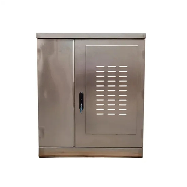
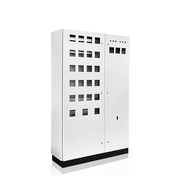
The distribution box is a crucial piece of equipment that connects solar panels to the AC power grid. Solar energy is a clean, renewable, and pollution-free source. A Solar Distribution Box plays a critical role in managing, controlling, and distributing electrical power safely within solar systems. Without it, the risk of electrical faults, system failures, and energy loss increases significantly. As solar adoption continues to rise globally, understanding. A panel junction box is typically mounted on the back of a solar module. It serves as the module's protected connection point—housing internal electrical terminations and enabling safe, standardized external connections via connectors. A PV combiner box is installed at the system level. Its primary. In modern solar PV installations, multiple strings of solar panels generate direct current (DC) power that must be safely consolidated, routed, and protected before it reaches the inverter. Handling high-voltage DC electricity requires precision and uncompromised safety measures. This essential device incorporates sophisticated protection mechanisms and monitoring capabilities to ensure.
[PDF]

The first thing you should do is locate the fiber optic cable that comes from the service provider. Once inserted, make sure it is securely. However, setting up a fiber optic connection to your router can seem daunting if you're unfamiliar with the process. Why Use Fiber Optic Internet? Before diving into the setup, let's quickly. Ensure your fiber optic router has an available WAN (Wide Area Network) or Ethernet port for the fiber optic modem. It's thin, flexible, and usually comes with connectors on both ends. Power Cables: Get power cables for both the. The fiber optic cable does not plug directly into a standard home router because the signal type must be translated. The fiber line terminates at the Optical Network Terminal (ONT), which is typically supplied and installed by the internet service provider. This specialized equipment serves as the. The process to connect fiber optic cable to router requires careful attention to detail, but I'll walk you through every critical step with the precision and clarity you deserve. Here's a step-by-step guide to help you through it. Understand the Basics Before diving in, familiarize yourself with the components involved:. Follow along as we take you through the step-by-step process of installing fiber internet! From preparing the site to connecting the final cables, we'll show you what goes into bringing high-speed internet to your doorstep. Whether you're a tech enthusiast or just curious about how it all w.
[PDF]

Here's a comprehensive guide to the 15 best optical power meters for fiber techs in 2025, offering expert insights and reviews to help you find the perfect tool for your needs. Also, please take a look at the list of 26 optical power meter manufacturers and their company rankings. Novanta Photonics, 3. What Is an Optical Power Meter? What Is an Optical Power Meter? An optical. | | | | | |. Optical power meters measure the average optical power (energy per unit time) of continuous-wave (CW) or high-repetition-rate pulsed light sources. They are distinct from optical energy meters, which measure the energy of single light pulses, although some consoles support both sensor types. They. Optical power meters and detectors have been served by Newport for over 30 years. The offering ranges from a low cost, hand-held meter to the most advanced dual channel benchtop power meter available in the market. Our 1936-R/2936-R series boasts state-of-the-art analog boards with a whopping 250. HPC-50BVhandheld optical power meter has compactsize and high reliability. It can make accurate measurement on seven operating wavelengths (850/980/1300/1310/1490/1550 /1625nm). ST800K-UC SC/ST/FC Li battery with USB, -70~+10 dbm optical power meter. Optical Power Meters from ADC Corporation are listed on GoPhotonics. Use the filters to.
[PDF]
The Huawei S5731-S24T4X is a switch from Huawei's S5731 series, designed for enterprise networks. It is a versatile and high-performance device that supports a range of applications, including data center, campus, and branch networking. The Xingmai Passive Ethernet Network (PEN) is an all-optical campus network solution based on the passive technology. Leveraging mainstream Ethernet protocols, the Xingmai PEN solution uses optical fibers to implement passive data transmission without the need of any ELV room. 24 Gigabit Ethernet Ports: Provides 24 10/100/1000 Mbps. Demand for Wi‑Fi 6-ready campus networks is growing rapidly, the Huawei S5732 Series empowers modern networks as a cutting-edge Aggregation Switch and Campus Switch, offering multi-Gigabit access, PoE++, and service intelligence. Its capabilities—from built-in WLAN AC to VXLAN and MACsec—ensure. CloudEngine S6780-H series switches are Huawei's next-generation enterprise-class core and aggregation switches that provide 64 x 100GE/32 x 25GE ports and 16 x 400GE optical ports. CloudEngine S5732-H hybrid optical-electrical.
[PDF]

There are 48 bicolor LEDs (green/amber) for the first 48 SFP+ ports and 16 tricolor LEDs (green/amber/white) for the SFP-DD ports. The last set of LEDs pulse once in white before indicating the FC port status in green or amber. When it blinks white twice, it shows the status of the second port of the SFP-DD. The port status LEDs for the FC ports are arranged left and right to correspond to the upper and lower ports respectively in each pair. LEDs on the port side of the switch Table 1. LEDs on Cisco Catalyst 9500 Series Switches 1 Available only on switches with 10G ports. System LED Indicator System is not operational. System is operating normally. As a group or individually, the LEDs show information about the switch and about the ports Preventing Overload - Each port that provides PoE has a maximum power it can deliver. Three LEDs are used on each port. Ports on the Cisco Catalyst switch do not have LEDs. Not the question you're searching for? Each. Number of LEDs per port - Ports that cannot be split; for example, 1G ports must have 1 LED per port. Location - A port LED should be placed right above the.
[PDF]

Switches come in three types: those with purely Ethernet ports, those with purely optical ports, and those with a combination of both. Port types are limited to two: optical and Ethernet. Optical ports on switches typically accommodate optical modules for. The optical ports on the switch are usually paired together, with one TX sender and one RX receiver. The. Optical switching represents a fundamental technological evolution, shifting data routing from the domain of electrons to the realm of photons, or light. This transition allows data to remain in its native optical form as it travels through fiber optic networks, eliminating the need for. An all-optical Ethernet switch is a network switch whose service ports are entirely optical, meaning every interface uses fiber rather than copper. This design enables end-to-end optical signal transmission, avoiding the conversion between electrical and optical signals at the switch port level. Copper ports, also known as RJ45 ports, are the most common type of Ethernet switch ports. These ports use twisted-pair copper cables (Cat5e, Cat6, Cat6a, etc. Copper ports are widely used in local area networks (LANs) due to their cost-effectiveness and ease of installation. They can function as core, aggregation, and access devices on campus networks and connect to upstream and downstream devices.
[PDF]

Wavelength: 1310nm, 1550nm, or CWDM/DWDM wavelengths. LR (Long Range): 10km, 1310nm, Blue latch. Each SFP module operates at a specific wavelength, and to avoid confusion, manufacturers use color-coded pull rings for easy identification. Here's a quick guide: 🔹 850nm (Black) – Short-distance multimode fiber (up to 550m) 🔹 1310nm (Blue) – Longer reach, typically used for single-mode fiber (up. Wavelength division multiplexing modules differ from other optical modules in center wavelengths. Wavelength division. Coarse Wavelength Division Multiplexing (CWDM) SFP modules are a practical and cost-effective solution for expanding network capacity while keeping equipment simple and scalable. Selecting the right wavelength for CWDM SFPs is essential to ensure optimal performance, minimal interference, and. Every optical transceiver operates at a specific wavelength, typically measured in nanometers (nm). Their pull. SFP (Small Form-factor Pluggable) is a compact, hot-swappable module used in network devices such as switches, routers, and servers to provide network connectivity and is widely used in network communications. Think of it as the “translator” for your network equipment, converting electrical signals into optical signals.
[PDF]
Locate your ONT/ONU: This is typically a small box provided by your ISP, often located near where the fiber optic cable enters your home. Connect the fiber optic cable: Plug the fiber optic cable from your ISP into the designated port on your ONT/ONU. This is usually clearly labeled. However, setting up a fiber optic connection to your router can seem daunting if you're unfamiliar with the process. In this guide, we'll walk you through how to connect a fiber optic cable to a router safely and efficiently. Why Use Fiber Optic Internet? Before diving into the setup, let's quickly. To set up your router for fiber internet quickly, connect the router to your fiber modem, access the router's settings via a web browser, and input the provided ISP credentials. Make sure to update the firmware, configure Wi-Fi security, and customize your network name for optimal performance. With. Setting up a fiber internet connection requires understanding key hardware components and following a specific connection sequence to establish your home network. Here's a simple guide to help you through the process: 1. Check Your Fiber Optic Equipment Before you start, make sure you have the necessary equipment: Fiber Optic Modem (ONT – Optical Network Terminal):.
[PDF]

Use two fibers: one dedicated to TX, the other to RX. Both sides transmit and receive at the same wavelength (common values: 850 nm MM, 1310 nm/1550 nm SM). The front panel is usually labeled TX and RX, and you cross-connect TX→RX, RX→TX with a duplex patch cord. Switch optical port intercommunication means that the optical fiber ports of two switches are connected to each other to achieve the purpose of network connection. The connection between two or more Ethernet switches in a certain way (Uplink port, etc. ) is called the cascade. SFP modules insert into these slots and and require two strands of fiber, typically duplex Using multi mode fiber (for runs under 1000 feet) or duplex single mode fiber (for runs over 1000 feet). This is a cost-effective and high performance way to connect network switches. Use one fiber strand for both. The switch supports 10 Mbps, 100 Mbps, and 1000 Mbps connections. Using Gigabit Ethernet (1000 Mbps), the switch sends files across the network at speeds up of to 2000 Mbps due to the full-duplex nature of Gigabit Ethernet connections. You can either connect 24 Ethernet copper cables or 22 copper. Port types are limited to two: optical and Ethernet. Optical ports on switches typically accommodate optical modules for transmitting data via fiber optic cables. In situations where there's a shortage of Ethernet ports, some users may insert Ethernet port modules into optical ports to connect with.
[PDF]
Step 3 Remove the cables or optical modules from the old card. Press the two green locking clips in the middle of the card to eject the ejector levers. Turn the ejector levers outward and slowly pull the card out. Place the replaced. Unplug the optical fibers from the optical module before removing it. Install or remove optical fibers carefully to avoid damaging the fiber connectors. If an optical module cannot be completely inserted into an optical. Page 7 Optical port USB storage device Wi-Fi terminal 1. Wear an ESD wrist strap or ESD gloves when replacing the optical module. Therefore, replace an optical module only when you confirm.
[PDF]

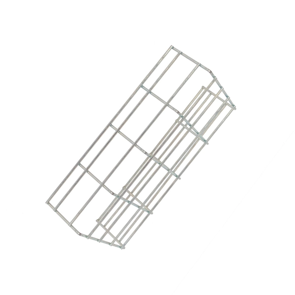
Cable Trays* — Max two 24 in. (610 mm) wide by max 6 in. (151 mm) deep open-ladder cable tray with channel-shaped side rails formed of 0. 54 mm) thick aluminum or min 0. In practice, cable tray dimensions are a system of interrelated measurements —width, depth, length, and material thickness—that directly affect cable fill compliance, heat dissipation, structural loading, and long-term expandability. From an engineering standpoint, cable tray dimensions are not. Perforated Cable Tray System expertly constructed from high-grade stainless steel, offering exceptional durability and resistance to corrosion. With side height 100mm. A properly designed and installed cable tray system will provide. Studs — Wall framing to consist of wood studs or channel shaped steel studs. Wood studs to consist of nom 2 by 4 in. Additional studs shall be used to completely frame. Best Size: Here, deep trays (75mm to 150mm) are used since power cables are typically thick and heavy. Data cables, such as your Wi-Fi or computer ones, are extremely sensitive. They do not get hot; however, they do not like to hang or sag. In case a data cable folds in an excessive manner, the. ect the minimum bend ra-dius for cables as they exit the bottom of the cable tray. A rung spacing of 6 to 9 inches (150 to 230 mm) is preferable when the cable tray cont d for instrumentation and control applications that require additional protec eferred to support and protect numerous small.
[PDF]

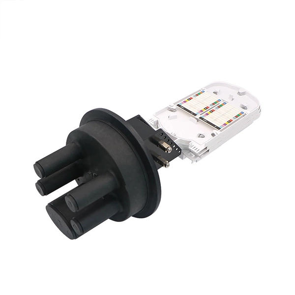
An Optical Splitter, also known as a beam splitter, is a passive optical device that divides a single input optical signal into two or more output signals. Conversely, it can also combine multiple signals into one. Knowing the difference between a splitter and an optical coupler helps you build better networks. You make your network work better when you pick the right device for each job. You can connect many users to one port with 1:n or 2:n splitters. By dividing a single optical signal from a central Optical Line Terminal (OLT) into multiple outputs for Optical Network Terminals (ONTs) at users' homes, splitters eliminate the need for dedicated fibers to each residence—slashing infrastructure costs while scaling network reach. This guide. In a Passive Optical Network (PON), a single optical fiber carries massive amounts of data using light. Signal Input: The fiber splitter receives the optical signal from the upstream network node and enters the splitter through the input fiber. Signal Distribution: Inside the splitter, according to the design structure and different. Splitters are passive optical devices that divide or combine optical signals, and they come in various types, including power splitters, uneven splitters, and wavelength-division multiplexing (WDM) splitters. Each type serves specific applications, enabling efficient use of optical infrastructure.
[PDF]
If your fusion splicer's battery isn't charging correctly, don't panic. There are a few things you can check before assuming the worst. The issue could be as simple as a faulty power cable, a loose connection, or a worn-out battery that needs replacing. Page 1 INSTRUCTION MANUAL ARC FUSION SPLICER F S M – 6 0 S Please read this instruction manual carefully before operating the equipment. Adhere to all safety instructions and warnings contained in this manual. Keep this manual in a safe place. Table of Contents Warning and Caution. ARC FUSION SPLICER 1 Table of Contents Warning and. Fujikura has been making the most reliable and hardest working splicers in the industry since the beginning of splicing. Your splicer isn't much help if it goes down in the. The FSm-60S fusion splicer sets the standard for core alignment fusion splicing by incorporating a user-friendly interface with enhanced features to provide the most rugged and reliable fusion splicer in the market today. The new rugged construction adds improved reliability by resisting shock. splicing machine Battery Repair Cells Replacement, make old battery better than new | Even U. Didn't See This Coming In order to make a good preparation before troubleshooting and repairing somehow problem of a splicer machine, FOT Telecom (www. com) team sharing this video: Learn.
[PDF]
Browse different network patch panel icons in unique different design styles. Patch panels are one of the best ways to manage an expansive local area network (LAN) by providing quick and easy access to the ports and connections that connect them altogether. They come in a range of sizes, and are typically mountable, whether that's on a wall, or on a rack to make for easier. Browse 10000 different network patch panel icons in 151 unique design styles. Download network patch panel icons. ICC's patch panel color icons were created to provide an easy color identification system specially designed for our cross-connect patch panels. They are available in nine colors. ITEM NUMBER DESCRIPTION ICMPPSCIxx* VOICE icons and DATA icons 6 pcs. ICMPPICVxx*. Icons (33) Photos. Find 33 Network Patch Panel images and millions more royalty free PNG & vector images from the world's most diverse collection of free icons. Get free icons of 48 patch panel in style for your design. You're also welcome to check new icons and popular. design styles for web or mobile (iOS and Android) design, marketing, or developer projects. These royalty-free high-quality Patch Panel Icons are available in SVG, PNG, EPS, ICO, ICNS, AI, or PDF and are available as individual or icon packs. You can also customize them to match your brand and.
[PDF]

How to install a fiber optic cable into a patch panel. Fibre Optic Patch Panel Installation Fibre Optic Cabling Know How - how to connect Fibre Optic Cable to a Patch Panel This video shows you how to install. Fiber optic patch panel is a crucial component in optical communications networks. It also known as a fiber patch panel or fiber distribution panel. It serves as a central point for organizing, managing, and connecting fiber optic cables. At its core, a fiber optic patch panel acts as a hub for. What are the best practices for fiber patch panel installation? The best practices below help to avoid installation issues and ensure ease of service for the system. Penetrate the enclosure from the side or bottom to minimize the risk of water intrusion. Step 1: Gather the Tools and Equipment The first step in connecting. How to Install a Fibre Optic Cable into a Patch Panel ( Fibre Optic Patch Panel ) How to install a fiber optic cable into a patch panel. This is essential for streamlining network. Running fiber internally involves extending this high-speed link from the service entry point to a centralized location, such as a dedicated media closet or network rack. This DIY effort is undertaken to maximize performance, improve aesthetics, or relocate the Optical Network Terminal (ONT) to a.
[PDF]