
Select the correct wavelength and set your reference. You measure optical power in dBm or insertion loss in dB. Consistent procedures ensure accuracy. Measure total signal loss from fiber, connectors, or splices. Optical fiber attenuation is the attenuation per unit length of optical fiber, and the unit is dB/km. When connecting two optical fibers, there will be loss inside any connector or joint. Consistent measurement techniques. While optical power meters are the primary power measurement instrument, optical loss test sets (OLTSs) and optical time domain reflectometers (OTDRs) also measure power in testing loss. TIA standard test FOTP-95 covers the measurement of optical power. Optical power is based on the heating power. Light Source: The CMA5 Series Light Sources provide an economical and stable laser source for use in point-to-point attenuation measurement. They feature a rugged design, built to withstand the difficult testing environment of fiber optic cable installation and maintenance. The CMA5 Light Sources. When talking about optical measurements, wavelength basically means how far a wave pattern repeats itself, usually measured in nanometers (nm). Commonly, a power meter on its own is used to measure absolute.
[PDF]

The OPM 510 and 520 are available in standard and high-power versions for the Telco and MSO markets. The OPM510 and OPM520 supports wavelengths of 850, 980, 1270 1300, 1310, 1490, 1550, 1577, 1623 and 1650nm. The rugged enclosure provides confidence when testing singlemode and. Count on Tempo Communications Optical Power Meters (OPM510/520) to test and maintain your fiber optic networks. Our optical power meters feature built-in calibration factors. Optical power meters and detectors have been served by Newport for over 30 years. The offering ranges from a low cost, hand-held meter to the most advanced dual channel benchtop power meter available in the market. Our 1936-R/2936-R series boasts state-of-the-art analog boards with a whopping 250. © Copyright© Santec Holdings Corporation. Demo the full range, from multi-use to dedicated PON and FTTH. VIAVI offers fast, cost-effective, and easy-to-use power meters for installation and maintenance of single mode and multimode fiber optic networks and. AFL is a trusted supplier of optical testing equipment with more than 30 years of experience and tens of thousands of units in use in the field. AFL's full range of power meters are used for testing single-mode and/or multimode fiber networks. Power meters with wave ID can detect two or more.
[PDF]

The core measurement procedure follows five steps: Turn on the meter and let it warm up. Most meters need a brief stabilization period before readings are reliable. Check your model's manual, but a minute or two is typical. Set the wavelength to match your light source. Fiber loss is the difference between the power when light is coupled from the transmitting end to the fiber and the power when the light reaches the receiving end. Generally speaking, when measuring the. An optical power meter measures the strength of light traveling through a fiber optic cable, giving you a reading in dBm (decibels relative to one milliwatt). The basic process is straightforward: turn the meter on, set it to the correct wavelength, clean your connectors, plug in, and read the. A power meter and light source are essential test tools that work in tandem to measure fiber optic cable loss and evaluate the quality of optical links. They provide the data necessary to quantify signal loss and pinpoint issues that could impact network performance. Here's how they work: A power. You measure optical power in dBm or insertion loss in dB. Verify light travels from transmitter to receiver. We'll give you the basic information you need and provide some printable references.
[PDF]

How to Use Optical Power Meter TR-504 | Optical Power Meter Working| Testing OPM, VFL, RJ45 | TRICOM In this video, we walk you through how to use the TRICOM TR-504 Optical Power Meter and explain how it works. Learn how to test fiber optic cables, OPM, VFL . Optical power meters are a key element in the optimization and maintenance of such optical networks and of their components. In this article, learn: What is an optical power meter? An optical power meter (OPM) measures the power levels of light signals in devices that transmit data or power using. An optical power meter measures the strength of light traveling through a fiber optic cable, giving you a reading in dBm (decibels relative to one milliwatt). The basic process is straightforward: turn the meter on, set it to the correct wavelength, clean your connectors, plug in, and read the. OPM interface: insert the fiber to be tested, test the optical power. An optical power meter is a tool that measures the number of optical power in a cable is fiber-optic. It helps engineers verify the performance of optical fiber systems, ensuring that the signal strength meets requirements, and is an essential tool for communication network maintenance and troubleshooting.
[PDF]
AFL Mexico and South America offers fiber optic cable, transmission and substation accessories, outside plant equipment, connectors, fusion splicers, test and inspection equipment. Identify and compare relevant B2B manufacturers, suppliers and retailers Max. The company offers training in real-world scenarios with experts, both virtually and in-person, focusing on fiber optic installation and network design. They provide certification and have expertise in optical splicing. [June 12, 2024 – Guadalajara, Mexico] Test Research, Inc. (TRI), the leading Test and Inspection systems provider for the electronics manufacturing industry, recently opened a new office in Guadalajara, Mexico, to accommodate the industry's rapid growth. TRI's expansion in Mexico emphasizes its. On August 8th, operations commenced at Yangtze Optics Mexico Cable S. in Mexico's Jalisco State, marking the establishment of Yangtze Optical Fibre and Cable Joint Stock Limited Company's (YOFC) first production facility in the nation. This development not only represents a significant. Minqing Fibramerica Technology, under its trade name FIBRAMÉRICA, is one of the world's leading companies dedicated to the design, development, manufacture, distribution and marketing of advanced optical connectivity solutions. We work closely with the main players in the telecommunications market.
[PDF]

This standard covers the construction, mechanical, electrical, and optical performance, installation guidelines, acceptance criteria, test requirements, environmental considerations, and accessories for a nonmetallic, all-dielectric self-supporting (ADSS) fiber optic cable. An All-Dielectric Self-Supporting (ADSS) cable operates without metallic messengers, relying entirely on its aramid yarn strength members. For a typical 12-fiber ADSS cable with a 8. AFL-ADSS® (All-Dielectric Self-Supporting) cable is ideal for installation in distribution as well as transmission environments. This guide provides general recommendations for the selection of methods, equipment, and tools for the stringing of ADSS (All Dielectric Self-upporting) fiber optic cables including short and Long Span ADSS cables. The installation methods for ADSS cables are essentially the same as those used for. This Installation Manual is a recommendatory installation document provided by HANGZHOU ZION COMMUNICATION CO. The installation manual is established based on the newest issued international standards such as lEEE Std 1222: 2004, "lEEE standard for all-dielectric. Round aramid reinforced ADSS cable for intermediate and long spans, 4 – 96 fibres. VDE: A- DF 2Y (ZN) 2Y This specification covers a family of optical cables with 4 - 96 fibres for intermediate and long spans.
[PDF]

By operating from a single 2. 5V input power rail and integrating the controller, gate driver, power inductor, and MOSFETs, these mini modules are optimized for space-constrained applications like optical modules, wearables, IoT, networking. SFP (Small Form-factor Pluggable) optical modules are compact, hot-pluggable transceivers that enable network equipment to connect seamlessly to fiber and copper links. These modules, including SFP, SFP+, and SFP28, are widely used in enterprise networks, data centers, and carrier-grade deployments. The optical module serves as a crucial component in optical fiber communication systems, operating at the physical layer, which is the lowest layer in the OSI model. Its primary function is to achieve optoelectronic conversion by converting electrical signals into optical signals and vice versa. Think of it as the “translator” for your network equipment, converting electrical signals into optical signals. As an essential component of optical fiber communication, optical modules are optoelectronic devices that facilitate the conversion between optical and electrical signals during the transmission process. They are essential in applications like telecommunications, data centers, and enterprise networks. Optoelectronic devices have transmitting and receiving modes.
[PDF]

It consists of 5 buttons. A power button, a button to turn on the VFL, a lambda button to set the wavelendth, a REF button, and a dBm/W button to set the unit of power. First, you check the initial power of a light signal. Then you check its power at the other end of optical. OPM interface: insert the fiber to be tested, test the optical power. REF/dB key: Short press the dB to switch unit, click once nW/dBm/dB to enter the upper clear data, press and hold until REF is displayed on the screen, and set the current optical power as reference value, enter the relative. There are two buttons on this meter. One is the power button, used to turn the meter on/off. At the top, there is a sensor that detects the light beam. The. at -22 (or 25 with tone on)). To do this you. Active Equipment Power Measurement Fiber Continuity Patch Cable Testing Check MM Reference Cables - Dual OWL MM Sources Check MM Reference Cables - WaveSource MM Sources Check SM Reference Cables - Laser OWL SM Sources Check SM Reference Cables - WaveSource SM Sources. Power-off: Press and hold “MODE” key for 2 seconds or more until “OFF” displays on the screen. Note: This instrument will shut down automatically without receiving any operation instruction for 10 minutes. Function selections: It.
[PDF]

Key finding: This paper develops analytical models and design procedures of ultra-wideband Wilkinson power dividers using linearly tapered transmission lines (TTLs) which provide size reduction and broadband performance. Read more. Power dividers are the passive electronic equipment used for splitting the power. They are now being employed in a variety of communications applications such as telephonic, antennas configurations, mobile connectivity, internet technology, & optics, etc. They come up with very low loss, operate at. RF and microwave power splitters and dividers create two copies of the same signal, while ideally preventing crosstalk between the outputs. Doing this with minimal loss while maintaining signal integrity is a challenge. In this article we explain how power splitters work and what the tradeoffs are. The rise of wireless connectivity requirements for applications such as Internet of Things (IoT), cellular, and automotive electronics is resulting in systems that are increasingly using RF signals, components, and subsystems. Often, designers need to direct these signals to more than a single. A power divider is a passive electronic device used in radio frequency (RF) and microwave applications to split an input signal into multiple output signals with equal or specified power levels, while maintaining impedance matching to minimize signal reflection and loss. How can power dividers.
[PDF]
In 1880, and his assistant created a very early precursor to fiber-optic communications, the, at Bell's newly established in. Bell considered it his most important invention. The device allowed for the of sound on a beam of light. On June 3, 1880, Bell conducted the world's first wireless transmission between two buildings, some 213 meters apart. Due to its use of an atmospher.
[PDF]

Optical Modules Market Segments - by Product Type (Transceivers, Receivers, Transmitters, Amplifiers, and Others), Application (Data Centers, Telecommunication, Enterprise Networking, and Others), Distribution Channel (Online Stores, Direct Sales, Indirect Sales . Optical Modules Market Segments - by Product Type (Transceivers, Receivers, Transmitters, Amplifiers, and Others), Application (Data Centers, Telecommunication, Enterprise Networking, and Others), Distribution Channel (Online Stores, Direct Sales, Indirect Sales . Data centers will keep dominating optical module demand as AI and cloud drive revenue growth through 2030. Optical module demand is being pulled in two directions at once, faster bandwidth for dense networks and tighter constraints on power, security, and lead times. 8% during the forecast period 2025-2031. The potential shifts in the 2025 U. tariff framework pose substantial volatility. The Optical Module Market size was estimated at USD 26. 53 billion in 2025 and expected to reach USD 30. The accelerating explosion of global data traffic has thrust optical modules into the heart of modern communications.
[PDF]

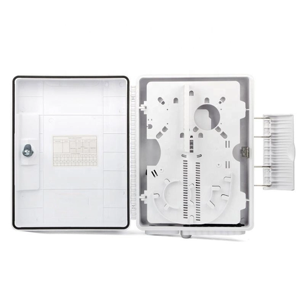
Here's a step-by-step guide to help you set up your fiber distribution box seamlessly: Before installing the fiber distribution box, ensure that your optical cables are properly prepared for connection. The optical fiber distribution box allows people to easily access the optical fibers in the box, and can well protect the optical fibers. In addition, the drawer structure also facilitates high-density wiring and good cable management. However, because optical fibers are fragile and can be easily. Keeping this page as a placeholder for now. Have any questions? Talk with us directly using LiveChat. Fix the rack to the ground with expansion bolts. Top installation: Dimensions of four connection holes on the top according to the. This instruction describes the installation of the Fiber Distribution Frame (FDF) manufactured by Corning Optical Communications. To order accessories that are purchased separately, contact Corning Optical Communications customer care for assistance. Read and understand this procedure (as well as. Optical fiber distribution frame is the wiring connection equipment between optical cable and optical communication equipment or between optical communication equipment. Distribution boxes are especially essential for FTTH networks, where they enable the efficient connection and management of optical fibers from a central.
[PDF]

A ceramic sleeve is a small, cylindrical element employing zirconia, which is a strong, low thermal expanding ceramic used in a fiber optic system to locally align and hold the interface between the fibers or connectors. It ensures precise alignment. Known for their high-temperature resistance, wear resistance, and chemical stability, ceramic sleeves have become a key element in applications spanning communications, electronics, automotive, aerospace, and industrial systems. The industry is developing in a diversified manner, connecting raw. Most of the ferrules used in optical connectors are made of ceramic (Zirconia) material due to some of the desirable properties they possess. Kyocera's extrusion molding process creates ferrules with excellent coaxiality, and our precision machining ensures excellent concentricity with precise. Alignment sleeves are the primary mechanical reference inside a fiber optic adapter. Their role is to constrain lateral offset, angular deviation, and axial separation between mating ferrules, directly determining insertion loss and return loss stability. Historically, both ceramic and phosphor. The global market for ceramic sleeves is experiencing robust growth, projected to reach an estimated $287 million by 2025. This expansion is fueled by an impressive CAGR of 20. 5% during the study period. The primary drivers for this surge are the increasing demand for high-performance optical.
[PDF]

The disruption of two undersea fibre optic cables left Kenyan Internet Service Providers and companies facing significant losses as services were severed, impacting internet users, international voice calls, and business operations. The incident was attributed to failures affecting the Seacom and EASSY (East African Submarine System) subsea cable systems. 1 million (KES 3 billion). The county government acknowledges the bill but insists Kenya. Kenya's fibre optic expansion is the most important project in Kenya's ambitious Digital Superhighway plan. The purpose is to raise fibre optic coverage of the country from 62% to 90% by the end of the next financial year. 04% in 2025, the market peaks at 17. Kenya's Fiber Optic Cable market is anticipated to experience a exponential growth rate of 16. 45%. Kenya cable market is witnessing a strategic pivot toward semi-automated smart cable manufacturing systems to address chronic import dependency and labor inefficiencies. With the country investing in local production hubs across key counties, the government and private sector are shifting attention. The Kenyan optical fiber cables market skyrocketed to $X in 2025, jumping by X% against the previous year. This figure reflects the total revenues of producers and importers (excluding logistics costs, retail marketing costs, and retailers' margins, which will be included in the final consumer.
[PDF]

This article provides a detailed technical comparison between fiber optic and copper cables, offering a clear perspective for engineers, network architects, and procurement managers. The core distinction between the two technologies lies in the physics of data. There are significant differences in performance between ADSS cables (all-dielectric self-supporting optical cables) and traditional optical cables, which are mainly reflected in the following aspects: 1. This type of fiber optic cable is designed to support its own weight without the need for additional support structures like messenger wires. The ADSS. There are several factors to assess when deciding which cable type is right for your application, including speed of connection for new customers, ease of changes and repairs, installer certification requirements, and the ability to expand the network over time. ADSS Fiber Optic Cables are a type of optical fiber cable designed specifically for. All-dielectric self-supporting (ADSS) cable is a type of optical fiber cable that is strong enough to support itself between structures without using conductive metal elements. It is used by electrical utility companies as a communications medium, installed along existing overhead transmission.
[PDF]
