Cable Trays* — Max two 24 in. (610 mm) wide by max 6 in. (151 mm) deep open-ladder cable tray with channel-shaped side rails formed of 0. 54 mm) thick aluminum or min 0. In practice, cable tray dimensions are a system of interrelated measurements —width, depth, length, and material thickness—that directly affect cable fill compliance, heat dissipation, structural loading, and long-term expandability. From an engineering standpoint, cable tray dimensions are not. Perforated Cable Tray System expertly constructed from high-grade stainless steel, offering exceptional durability and resistance to corrosion. With side height 100mm. A properly designed and installed cable tray system will provide. Studs — Wall framing to consist of wood studs or channel shaped steel studs. Wood studs to consist of nom 2 by 4 in. Additional studs shall be used to completely frame. Best Size: Here, deep trays (75mm to 150mm) are used since power cables are typically thick and heavy. Data cables, such as your Wi-Fi or computer ones, are extremely sensitive. They do not get hot; however, they do not like to hang or sag. In case a data cable folds in an excessive manner, the. ect the minimum bend ra-dius for cables as they exit the bottom of the cable tray. A rung spacing of 6 to 9 inches (150 to 230 mm) is preferable when the cable tray cont d for instrumentation and control applications that require additional protec eferred to support and protect numerous small.
[PDF]
If you encounter any of these issues, check the optical connector for damage or dirt, inspect the fiber optic patch cord, ensure the optical module is correctly installed, and check the device settings for compatibility. Subsequently, the driver semiconductor laser (LD) or light-emitting diode (LED) emits modulated optical signals at the corresponding rate. After transmission through the optical fiber, the receiving interface converts the optical signals into electrical signals using a photodetector diode and. An optical module is a typically hot-pluggable optical transceiver used in high-bandwidth data communications applications. Optical modules typically have an electrical interface on the side that connects to the inside of the system and an optical interface on the side that connects to the outside. The Transmitter Optical Sub Assembly (TOSA) is responsible for the emission of light. Its primary function entails converting electrical signals into optical signals.
[PDF]

Beam splitters are classified by construction (plate, cube, pellicle, polka dot) and by function (standard, non-polarizing, polarizing, dichroic). Construction determines ghosting, damage threshold, and form factor. Function determines how polarization and wavelength are. Beamsplitters are optical components used to split incident light at a designated ratio into two separate beams. Additionally, beamsplitters can be used in reverse to combine two different beams into a single one. Beamsplitters are often classified according to their construction: cube or plate. A beam splitter (or beamsplitter, power splitter) is an optical device which can split an incident light beam (e. a laser beam) into two (or sometimes more) beams, which may or may not have the same optical power (radiant flux). It is a crucial part of many optical experimental and measurement systems, such as interferometers, also finding widespread application in fibre optic telecommunications. It is also possible to combine the separated beams. Types of Beam Splitters 2. They are found in different configurations and can be used in multiple applications. However, how they work exactly often remains overlooked. These versatile tools can split both laser and regular light, depending on the application in question.
[PDF]
A beam splitter or beamsplitter is an optical device that splits a beam of light into a transmitted and a reflected beam. It is a crucial part of many optical experimental and measurement systems, such as interferometers, also finding widespread application in fibre optic telecommunications. DesignsIn its most common form, a cube, a beam splitter is made from two triangular glass which are glued together at their base using polyester,, or urethane-based adhesives. (Before these synthetic,. Beam splitters are sometimes used to recombine beams of light, as in a. In this case there are two incoming beams, and potentially two outgoing beams. But the amplitudes. For beam splitters with two incoming beams, using a classical, lossless beam splitter with Ea and Eb each incident at one of the inputs, the two output fields Ec and Ed are linearly related to the inputs thro.
[PDF]

The core measurement procedure follows five steps: Turn on the meter and let it warm up. Most meters need a brief stabilization period before readings are reliable. Check your model's manual, but a minute or two is typical. Set the wavelength to match your light source. Fiber loss is the difference between the power when light is coupled from the transmitting end to the fiber and the power when the light reaches the receiving end. Generally speaking, when measuring the. An optical power meter measures the strength of light traveling through a fiber optic cable, giving you a reading in dBm (decibels relative to one milliwatt). The basic process is straightforward: turn the meter on, set it to the correct wavelength, clean your connectors, plug in, and read the. A power meter and light source are essential test tools that work in tandem to measure fiber optic cable loss and evaluate the quality of optical links. They provide the data necessary to quantify signal loss and pinpoint issues that could impact network performance. Here's how they work: A power. You measure optical power in dBm or insertion loss in dB. Verify light travels from transmitter to receiver. We'll give you the basic information you need and provide some printable references.
[PDF]

A wiring diagram for a photocell and timeclock controller provides a step-by-step guide for installing and connecting all the components in a light system. It shows exactly how each component fits into the overall scheme of things, as well as what wires to use and which connections to. Intelligent Lighting Controls' wiring diagrams show detailed schematics of our solutions. A lighting control module is the “control center” for your lighting system. It acts as a bridge between your physical lighting fixtures and the smart systems that manage them. Instead of relying solely on traditional wall switches, you can control your lights via remotes, mobile or web apps. This guide will discuss the steps needed to integrate with URC Total Control. Commission CSI Controllers Step 2. Locate/Download latest TCM files/Module Step 3. Network Setup Step 6. Supports DALI V2 compatible switches and sensors, works out of the box. Simple and easy setup. ControlByWeb® IoT controllers are a great fit for lighting control in edge applications. Understanding the components that make up a modern lighting system, and how they relate to one another is key to ensuring the best performance and.
[PDF]
In general, foreign suppliers enter the Chilean market by appointing an agent, distributor, or wholesaler. Most are small-to-medium size firms. Several large firms handle different product lines and operate a.
[PDF]

This report describes a set of five field evaluations conducted by Pacific Northwest National Laboratory (PNNL) and DesignLights Consortium for U. Department of Energy, between November 2015 and September 2017, to demonstrate the potential energy-savings capability of advanced . Lighting systems define the difference between a toy grade machine and a professional-grade scale crawler. Choosing the right controller dictates how that light behaves, moving beyond simple on-off switches into the realm of true scale realism. Integrating these systems transforms a static rig into. What Defines a Great Lighting Control System in 2025? 1. Lutron (Vive & Quantum): The Scalable Market Leader 2. DALI (Digital Addressable Lighting Interface): The Open Protocol Standard 3. Crestron: The King of High-End Integration 4. Casambi: The Leader in Bluetooth Mesh Wireless Control 5. PoE. These systems provide a consolidated method for managing all of your home's lights using a single app or device. However, choosing from the wide range of available options might be challenging. To assist you in making a wise choice, we have put together a guide to the top home lighting control. re being properly set up and tested for the Program Administrators (PAs). These criteria will ease the decision-making around the appropriate savings factors and incentive levels that projects can claim. By combining technical parameters with hands-on project experience, it supports designers.
[PDF]

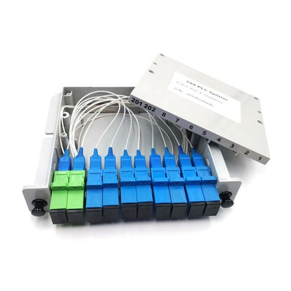
An Optical Splitter, also known as a beam splitter, is a passive optical device that divides a single input optical signal into two or more output signals. Conversely, it can also combine multiple signals into one. Knowing the difference between a splitter and an optical coupler helps you build better networks. You make your network work better when you pick the right device for each job. You can connect many users to one port with 1:n or 2:n splitters. By dividing a single optical signal from a central Optical Line Terminal (OLT) into multiple outputs for Optical Network Terminals (ONTs) at users' homes, splitters eliminate the need for dedicated fibers to each residence—slashing infrastructure costs while scaling network reach. This guide. In a Passive Optical Network (PON), a single optical fiber carries massive amounts of data using light. Signal Input: The fiber splitter receives the optical signal from the upstream network node and enters the splitter through the input fiber. Signal Distribution: Inside the splitter, according to the design structure and different. Splitters are passive optical devices that divide or combine optical signals, and they come in various types, including power splitters, uneven splitters, and wavelength-division multiplexing (WDM) splitters. Each type serves specific applications, enabling efficient use of optical infrastructure.
[PDF]
Fiber Strippers: These are specialized tools designed to peel away the outer buffer and the microscopic coating of the fiber without scratching or nicking the glass core. High-Precision Cleaver: You cannot use scissors or standard snips for this. The most efficient way to terminate a fiber run is by using a pigtail. A fiber pigtail is a short length of optical fiber that comes with a high-quality, factory-polished connector already installed on one end, leaving a length of exposed glass on the other. Instead of building a connector from. Executive Summary: A fiber optic pigtail is one of the most commonly specified yet least understood components in structured cabling. Get the wrong connector type, the wrong polish, or skip proper fusion splicing technique—and you're looking at elevated signal loss, increased back reflection, and a. In this detailed video, we'll walk you through the fiber optic pigtail splicing process — from preparation to final testing. If you're new to fiber optics or want to enhance your technical skills, this guide will help you understand how to splice fiber pigtails safely and efficiently. In this article, we will explore what fiber optic pigtails. Fiber pigtails are simple in appearance, yet essential in function. They are the bridge between fiber optic cables in the field and the equipment or patch panels that manage them.
[PDF]
By adopting the TIA/EIA‑598C standard, you gain a universal “language” of colors that speeds identification, reduces miswiring, and enhances safety across cable jackets, connectors, buffer tubes, and splice trays. Understanding fiber‑optic color codes is essential for any technician tasked with installing, maintaining, or troubleshooting modern fiber networks. The TIA-598-D standard defines a standardized color-coding system that engineers and technicians rely on to identify different types of fiber optic cables, connectors, and individual. Fiber optic cables are the arteries of modern communication—from data centers to factories, these slim strands of glass move terabits of information every second. But with thousands of fibers in a single cable, color coding is your universal translator. Without it, you'd be lost in a spaghetti mess. Fiber optic color codes provide the essential identification framework that enables fiber technicians and network professionals to manage complex optical network installations efficiently. This guide explains how standardized fiber strands, cable jackets, connectors, and MPO systems simplify identification, prevent mismatches, and maintain signal integrity. These codes ensure correct organization and connectivity during installation or maintenance processes. The colors typically follow a color scheme established by industry.
[PDF]

This is the first and crucial connection—attach the incoming live wire (typically marked with brown or red insulation) to the main terminal in the distribution box. Before you begin installing a distribution box, make sure you have the right tools and materials. Below is a quick checklist of everything you will need for a safe and efficient installation: Connecting a distribution box involves several steps to ensure proper electrical flow. Follow this guide. Applications - The minimally invasive retrofit kit enables the opportunity existing remote power infrastructure cross arm, & wiring) providing the total cost of ownership. Failure to strictly adhere to the warnings and cautions as well as the installation instructions may result in serious personal. Hey, in this article we are going to see the Single Phase Distribution Box Wiring Diagram and Connection Procedure. Whether you're an electrician or a DIY enthusiast, this guide will help you understand the basics of home electrical distribution. What is Distribution Board? Distribution board. Power source through switch box - When power comes through a box containing a light switch and continues on to the light, the switch is attached on one terminal to the black (or sometimes red) line from the power source and on the other terminal to the black (or red) line going on to the light.
[PDF]
Fixed fiber optic attenuators are used to reduce the optical power signal in communication links. They work analogous to a step-down transformer. As the signal approaches a device or node in a communication link the power is reduced to a level that is suitable for its application. They are used to control the power level of optical signals at the outputs of light sources and electrical-to-optical (E/O) converters. Measured in decibels (dB), loss degrades signal quality, limits distance, increases bit-error rate, and escalates infrastructure cost. Understanding and managing it is critical to. The Fiber optic attenuator is an optical device that reduces the energy of the optical signal—used to attenuate the input optical power to avoid the distortion of the optical receiver due to the input optical power being too strong. It works by dissipating a portion of the optical power passing through it, thereby lowering the overall power level. Fiber optic attenuators.
[PDF]
Single-mode optical modules use LD (Laser Diode) or LEDs with a narrow spectral line as the light source. Single - mode optical modules are used for long - distance transmission, generally over 10km, and can reach. Signal Transmission: Single-mode fiber transmits light in a single path. This keeps signal loss and dispersion low for longer distances. Multi-mode fiber disperses light in multiple paths. I've seen people use a single-mode. In fiber-optic communication, a single-mode optical fiber, also known as fundamental- or mono-mode, is an optical fiber designed to carry only a single mode of light - the transverse mode. This article explores what single-mode fibers are, how they are designed, and their applications in various fields. It has a narrow core diameter of 8-10 microns and uses a laser or highly-focused light source to send light signals down the fiber.
[PDF]
Dichroic Mirror split light or beam based on their wavelength (or color). example : transmit red light and reflect green light. Additionally, beamsplitters can be used in reverse to combine two different beams into a single one. Beamsplitters are often classified according to their construction: cube or plate. A beam splitter or beamsplitter is an optical device that splits a beam of light into a transmitted and a reflected beam. It is a crucial part of many optical experimental and measurement systems, such as interferometers, also finding widespread application in fibre optic telecommunications. In its. 📦 For purchasing, use the RP Photonics Buyer's Guide for beam splitters. It provides an expert-curated supplier directory, buyer-focused technical background information, and structured selection criteria to support professional procurement decisions. What are Beam Splitters? A beam splitter (or. The beam splitter splits and then recombines infrared radiation, while the detector picks up the resulting signal. It's sensitive to both intensity and frequency. Together, they decide just how accurately an instrument captures those unique infrared “fingerprints” from different substances. A beam. These optical components divide incident light into two distinct beams: one reflected and one transmitted. This precise ability to direct light paths makes beam splitters essential in various applications, including imaging systems, laser systems, and telecommunications.
[PDF]