
To use a power meter for fiber optic testing, always clean connectors first with lint-free wipes or click-to-clean tools. Select the correct wavelength and set your reference. You measure optical power in dBm or insertion loss in dB. Consistent procedures ensure accuracy. Verify light travels from. The most basic fiber optic measurement is optical power from the end of a fiber. This measurement is the basis for loss measurements as well as the power from a source or presented at a receiver. Typically both transmitters and receivers have receptacles for fiber optic connectors, so measuring the. An optical power meter measures the strength of light traveling through a fiber optic cable, giving you a reading in dBm (decibels relative to one milliwatt). This article will guide you through the methods, instruments, and key considerations for measuring fiber. Fiber optic cabling is the high-performance core of today's datacom networks. As network speeds and bandwidth demands increase, fiber performance requirements have become more stringent. Fiber testing is more important than ever. An OPM uses a photodiode to generate an electrical current proportional to optical power.
[PDF]
Power consumption of fiber optic cables can range from 0. 01-100 W/Gbps depending on the length of the cable (chart below). To ensure that fiber-optic connections have sufficient power for correct operation, calculate the link's power budget when planning fiber-optic cable layout and distances. The power budget is. Attenuation is the difference between the launch power of the signal from the transmitter and the power of the signal at the receiver. Each. The power consumption of coherent fiber-optical communication systems is beco-ming increasingly important, for both environmental and economical reasons. The data traffic on the Internet is increasing at a faster pace than that at which optical network equipment is becoming more energy efficient. With the growing global deployment of Fiber-to-the-Home (FTTH) networks driven by the demand for ensuring high-capacity broadband services, mobile network operators (MNOs) face challenges of excessive energy consumption (EC) of wired optical access networks (OANs). You use power budget calculations to verify whether an optical link—FTTH, ODN, backbone, or data center—can operate reliably under all. Reduced power consumption: 800G optical devices can achieve energy savings at the optical and system level, such as using more efficient modulation formats, optimizing circuit design, and reducing power density.
[PDF]

Fiber optic loss calculation formula: Total link loss (LL) = Cable attenuation + Connector attenuation + Fusion attenuation [Note: If there are other components (such as attenuators), their attenuation values can be added]. Intrinsic Optical Fiber Losses comprise of absorption loss, dispersion loss and scattering loss caused by the structural defects. The detailed information about these optical losses and how to reduce them are. Calculate fiber optic signal loss based on cable length, attenuation, and connector losses. Determine cable loss, connector loss, and total system loss in decibels (dB) to assess signal quality and repeater requirements. Fiber optic loss is calculated in two parts: cable loss and connector loss. This calculator determines fiber loss based on input power, output power, and the length of the fiber optic cable. In summary, fiber optic loss is. Use this worksheet to input values for all variables that will impact your system's performance. After entering your values, please ensure you click the 'Calculate Link Loss' button at the bottom of the page to generate your total link loss. This step is necessary to see if your system falls within. Optical fiber loss is a term for signal loss affecting transmission reliability. Optical fiber loss is.
[PDF]
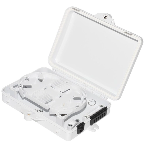
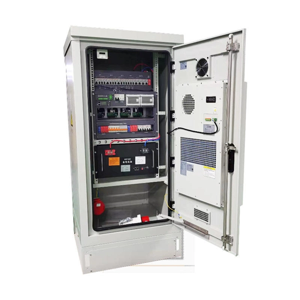
A distribution box serves as a central point for managing and distributing fiber optic cables. This device ensures reliable and efficient connectivity between various network components. The importance of a distribution box cannot be. Fiber distribution box is made of high-strength engineering plastics, anti-UV, anti-aging ability. This article provides a comprehensive overview of fiber optic distribution boxes, essential components in modern telecommunications networks that enhance data transmission efficiency and reliability. Why do operators, designers, and installers use additional fiber optic hardware racks for cable and fiber management? The active electronics are the most expensive part of the. Enter the Optical Distribution Frame (ODF)—a foundational component that serves as the “nerve center” for fiber optic management, enabling seamless connectivity, efficient maintenance, and scalable growth. This guide demystifies ODF, exploring their design, core functions, types, and how they. Embodying Clearfield's commitment to modularity and flexibility, our FieldSmart Active Cabinets are rigorously tested and certified to safeguard critical infrastructure in even the most challenging environments. Designed with innovative options for fiber and active equipment craft separation, these.
[PDF]

When you look at a fiber optic cable, the outer jacket color instantly tells you what type of fiber is inside. This color-coding system is standardized under TIA-598-C, making it easier for technicians and installers to identify cables at a glance. By adopting the TIA/EIA‑598C standard, you gain a universal “language” of colors that speeds identification, reduces miswiring, and enhances safety across cable jackets, connectors, buffer tubes, and splice trays. Error Reduction: A standardized palette prevents costly mis‑splices and. In fiber communications, the color of the fiber is not only an eyes-only indicator—it is actually used for determining the quantity, type of the fiber, and use of the fiber. Every fiber is color-coded, and this is a very crucial detail in the installation process, maintenance procedure, and. The fiber optic color codes refer to a standardized system used to identify individual fibers within a particular cable. These codes ensure correct organization and connectivity during installation or maintenance processes. The colors typically follow a color scheme established by industry. To solve this, the industry relies on an authoritative color-coding system: the EIA/TIA-598 Standard, which provides unified guidelines for identifying optical fibers, cable jackets, buffer tubes, and connectors.
[PDF]
Bulk purchases typically come with discounts, making it more cost-effective for large-scale projects. Conversely, single or small quantity orders may incur higher per-unit costs. As of recent market analysis, the price range for OPGW cables is generally between RMB 10,000 to RMB 30,000. Fiber-optic cable materials typically cost $1 to $6 per linear foot, depending on fiber count and cable type. Commercial building installations with 100-200 network drops generally range from $15,000 to $30,000. Single-mode fiber costs less per foot than multimode fiber, but it requires more. Large core fibers from Fibercore. Highly customizable designs with a wide range of coatings available. Offering unique properties and benefits for different types of use, 8 core armoured cable Fiber Optic om3 multimode. TMT GLOBAL Fiber Optic Cable offers a high-quality multimode 8. Large core multimode optical fiber with core diameters from 10 ~ 2000µm provide ease of alignment and enable light/laser transmission with high power efficiency. A wide variety of silica core and silica clad optical fibers to cover a broad spectrum of wavelength ranges from deep ultraviolet (DUV). 20-meter hdmi 2. 0v fiber optic cable designed for high-resolution video transmission. Fiber Visual Fault Locator,10KM VFL Fiber Optic Cable Tester,Network Fiber Cable Test Fiber Light. 5m mtp 10gb 50/125 om3 multimode pvc fiber optic cable - aqua.
[PDF]

Optical connectors are the physical interface that links an optical device to a fiber optic cable. Fiber optics are used in many applications, including medical imaging, automotive, military, industrial, and commercial (e., telecommunications). Each of these. Many people ask the same question: Can you use a fiber optic cable with an RJ45 port? The short answer is no - RJ45 connectors are designed for electrical Ethernet signals, while fiber optics transmit light pulses through glass or plastic. However, modern networks often combine both technologies. An optical fiber connector is a device used to link optical fibers, facilitating the efficient transmission of light signals. An optical fiber connector enables quicker connection and disconnection than splicing. They come in various types like SC, LC, ST, and MTP, each designed for specific. Proper connection of fiber optic cables is essential to harness these benefits fully, as even minor errors can lead to significant performance issues like signal loss. This article will guide you through the necessary tools, materials, and methods on how to connect fiber optic cables effectively. Most SFP fiber optic modules use LC connectors, while SC connectors are mainly found in legacy networks and MPO/MTP connectors are used for high-density cabling rather than directly on standard SFP modules. FC FO LC connectors for fiber optic.
[PDF]

In short length cables a visual fault locator (VFL) can find where the cut is or find the bad connector at patch panels. For longer distance cables, the use of an OTDR is required. Once the fault is located, fusion splicers and splice-on connectors can be used to complete the repair. Fiber optic cables are the backbone of modern networks, delivering fast and reliable data transmission. Accidental cuts, breaks, or other damage can disrupt your network and cause costly downtime. With the right tools and techniques, you can efficiently repair damaged fiber cables and restore. Fiber optics offers advantages like EMI immunity and low attenuation (0. 2 dB/km), but it's fragile—susceptible to breaks, bends, and contamination. Repairs focus on restoring the light path with minimal signal loss (<0. A fusion. Visual inspection and specialized tools like OTDRs, OPMs, and VFLs are essential for identifying and locating physical damage or faults in fiber optic cables. Emergency restoration planning involves implementing backup power solutions, network redundancy planning, and strategies for prompt. Fiber optic cables are critical components of modern communication networks, transmitting vast amounts of data at lightning speeds.
[PDF]

This section provides an overview for optical power meters as well as their applications and principles. Our list of suppliers for that category contains 69 suppliers. Understand the Technical Background To support your technical evaluation, this section includes links to authoritative encyclopedia articles for in-depth verification of the underlying physics, technical issues and techniques. Market Forecast By Type (Thermal Detectors, Photo Detectors), By Instrument/Product Type (Benchtop Meter, Portable Meter, Virtual Meter, Optical Wavelength, Hand-Held Meter, Others), By Detector Type (InGaAs (Indium Gallium Arsenide), Germanium, Silicon, Others), By Power Range (High, Medium, Low). This section provides an overview for optical power meters as well as their applications and principles. Here are the top-ranked optical power meter companies as of May, 2026: 1. Novanta. Photon Systems, Inc. designs, develops, manufactures and markets deep ultraviolet lasers and incoherent sources, instruments based on these sources, and optical and electro-optical accessories for a broad range of applications primarily within the. All of EXFO's modular (IQS line) and benchtop power meters are built for top performance and pinpoint accuracy, and the various models offer a mixture of features and specifications to suit various test setups. Fast, accurate, flexible power. © Copyright© Santec Holdings Corporation.
[PDF]
In 1880, and his assistant created a very early precursor to fiber-optic communications, the, at Bell's newly established in. Bell considered it his most important invention. The device allowed for the of sound on a beam of light. On June 3, 1880, Bell conducted the world's first wireless transmission between two buildings, some 213 meters apart. Due to its use of an atmospher.
[PDF]

Select the correct wavelength and set your reference. You measure optical power in dBm or insertion loss in dB. Consistent procedures ensure accuracy. Measure total signal loss from fiber, connectors, or splices. Optical fiber attenuation is the attenuation per unit length of optical fiber, and the unit is dB/km. When connecting two optical fibers, there will be loss inside any connector or joint. Consistent measurement techniques. While optical power meters are the primary power measurement instrument, optical loss test sets (OLTSs) and optical time domain reflectometers (OTDRs) also measure power in testing loss. TIA standard test FOTP-95 covers the measurement of optical power. Optical power is based on the heating power. Light Source: The CMA5 Series Light Sources provide an economical and stable laser source for use in point-to-point attenuation measurement. They feature a rugged design, built to withstand the difficult testing environment of fiber optic cable installation and maintenance. The CMA5 Light Sources. When talking about optical measurements, wavelength basically means how far a wave pattern repeats itself, usually measured in nanometers (nm). Commonly, a power meter on its own is used to measure absolute.
[PDF]

Learn how to monitor SFP optical power on Cisco switches, interpret Tx/Rx levels, and troubleshoot fiber link issues. Step-by-step CLI commands, model-specific guidance, and best practices included. In this article, we will break down the key factors influencing TX/RX power, explain how to calculate the optical power budget, and provide actionable insights for optimizing your network's performance using SFP modules. SFP (Small Form-Factor Pluggable) modules are compact transceivers that allow. SFP (Small Form-factor Pluggable) optical modules are compact, hot-pluggable transceivers that enable network equipment to connect seamlessly to fiber and copper links. Even if an interface appears up, degraded Tx/Rx levels can cause intermittent flapping, packet loss, or err-disabled states. Think of it as the “translator” for your network equipment, converting electrical signals into optical signals. The most two important factors of the SFP transceiver: Output power (TX power) and receiver sensitivity (RX sensitivity). The optical TX power is the signal level leaving from that device, which should be within the transmitter power range. The RX sensitivity is the incoming signal level being. In current network communication, SFP optical modules are an indispensable physical foundation for building network channels. They form high-speed channels for optical signal transmission. Therefore, to ensure their.
[PDF]

Communication networks are an integral part of interconnected transmission lines in a power grid, analogous to the spinal cord for control signal and information exchange among substations, data hubs, and load dispatch centers. This article cov. Communication networks are an integral part of interconnected transmission lines in a power grid, analogous to the spinal cord for control signal and information exchange among substations, data hubs, and load dispatch centers. This article covers the major trend and design aspects of fiber optics communication link in power transmission line netwo. The communication network in the power grid is one of the most interrelated systems that require perfect compliance in equipment and protocol selection. While the high voltage components are relatively unchanged over decades in terms of operating principles, the communication protocols and equipment are seeing astonishing advancements every year. S. 2.1 Knowhow of prevailing setupWhile the primary objective is always to get the best solution for the lowest price, in the case of extension projects, the design engineers must also keep an eye on the existing setup. The issue of back-compatibility and upgradationsshould be properly accessed in existing equipment, even more so in the case of proprietary legacy setups. Figure below illustrates one such group of communication equipment in existing substations that might need proper interfacing and compatibility adapters befo.
[PDF]

This standard covers the construction, mechanical, electrical, and optical performance, installation guidelines, acceptance criteria, test requirements, environmental considerations, and accessories for a nonmetallic, all-dielectric self-supporting (ADSS) fiber optic cable. An All-Dielectric Self-Supporting (ADSS) cable operates without metallic messengers, relying entirely on its aramid yarn strength members. For a typical 12-fiber ADSS cable with a 8. AFL-ADSS® (All-Dielectric Self-Supporting) cable is ideal for installation in distribution as well as transmission environments. This guide provides general recommendations for the selection of methods, equipment, and tools for the stringing of ADSS (All Dielectric Self-upporting) fiber optic cables including short and Long Span ADSS cables. The installation methods for ADSS cables are essentially the same as those used for. This Installation Manual is a recommendatory installation document provided by HANGZHOU ZION COMMUNICATION CO. The installation manual is established based on the newest issued international standards such as lEEE Std 1222: 2004, "lEEE standard for all-dielectric. Round aramid reinforced ADSS cable for intermediate and long spans, 4 – 96 fibres. VDE: A- DF 2Y (ZN) 2Y This specification covers a family of optical cables with 4 - 96 fibres for intermediate and long spans.
[PDF]

Arduino-Powered Data Transmission with Fiber Optics Welcome to our video tutorial on optical communication with Arduino, designed to be easy t. more. They consist of a transmitter on one end of a fiber and a receiver on the other end. Most systems use a "transceiver" which includes both transmission and. I'm going to use HFBR 1414 fiber optic transmitter module which is manufactured by Broadcom. It is a low-cost high-power transmitter that is designed for use in industrial power generation, power distribution, medical transportation and gaming applications. Internally, the optical fiber consists of a highly reflective central core, which acts like a light guide. Media converters are special fiber optic transceivers used to convert from one type of cable (the media) to another, typically from copper cables to fiber optics, although some media converters will convert from one fiber type to another, e. multimode to singlemode. The FOA Guide has a page about. A fiber optic transceiver (also called an optical transceiver) is a compact module that both transmits and receives data signals through optical fibers. It serves a dual purpose — transmitting electrical signals as light pulses and receiving light pulses to convert them back into electrical form.
[PDF]
