In this tutorial, I will show you how you can connect the Optocoupler to Arduino, read the data as Analog or Digital, and if necessary convert the analog values to digital, and how to reduce noise from the sensor. The Infrared Slotted Optical Optocoupler Module is a device that uses infrared light to transmit signals between two electrically isolated circuits. It consists of an infrared emitter (LED) and a photodetector (phototransistor) housed in a slotted enclosure. When an object passes through the slot. Slotted Optocouplers (Photo Interrupters) are very useful sensors, often included in Arduino projects to detect position of moving objects, measure speed of rotation, or linear motion, frequency of events, and many others. They are easy to use, but it is important to understand how they work, so. This tutorial is a comprehensive, practical guide to the Speed Sensor / Tacho Sensor (Slot-Type Optocoupler) (Leobot Product #245). Moreover, a simple application is programmed that shows how to wire and how to program an Arduino when working with the module. In this tutorial, the module is used as an “digital input board”. If you want to use the. In this project, I will talk about Phototransistor Optical Interrupter Switches (Opto Coupler) Module, how this module works and helps in determining the speed of a rotating object and finally I will show you how to Interface Optical Interrupter Switch Sensor with Arduino and measure the speed of a.
[PDF]
A beam splitter or beamsplitter is an that splits a beam of into a transmitted and a reflected beam. It is a crucial part of many optical experimental and measurement systems, such as, also finding widespread application in.
[PDF]

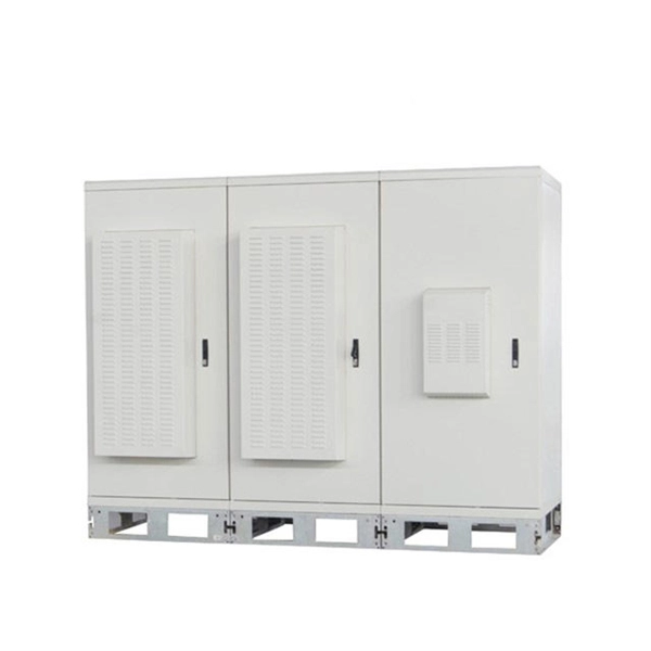
In modern FTTH architectures, the ODN is the physical fiber layer that distributes optical signals from the central office to end users. Operators consider ODN design as one of the most important factors affecting: Network coverage Optical loss performance Deployment cost. This passive layer is known as the Optical Distribution Network (ODN). Its role is to provide an optical transmission channel between the OLT and the ONU. The ODN network design is a physical facility that connects the communication room and user equipment, and is a key component. Short summary: The Optical Distribution Network (ODN) is the passive infrastructure linking the central office to the subscriber in FTTH. This guide delves into essential ODN components like splitters, distribution boxes, and ODFs, showcasing how Hainan ZTO Cable Co. It's the silent, robust highway that delivers blazing-fast Fiber-to-the-Home (FTTH) and 5G services. The maximum permissible optical power attenuation between OLT optical ports to ONT input is 28dB, which is by utilizing the so-called Class B optical network. At the heart of every Fiber-to-the-Home (FTTH) deployment lies the Optical Distribution Network (ODN) — a meticulously engineered passive infrastructure that enables operators to deliver massive bandwidth, low latency, and reliable service to millions of users. The ODN connects the Optical Line.
[PDF]

The optocoupler can be used in many different applications as an interface between low voltage digital, such as 3. 3V logic, or 24V control circuits and large mains power electronic devices. Thus protecting sensitive circuits (e., microcontrollers) from high-voltage supplies. Optocouplers, also known as opto-isolators, uses infrared light to transfer electrical signals between two electrically isolated circuits and are commonly classified by their photosensitive output device What is an Optocoupler? An optocoupler (also called an opto-isolator, photo-coupler, or optical. Optocouplers become specifically useful where an electrical signal is required to be sent across two circuit stages, but with an extreme degree of electrical isolation across the stages. Optocoupling devices work as logic level changeovers between two circuits, It has the ability to block noise. An opto-isolator (also called an optocoupler, photocoupler, or optical isolator) is an electronic component that transfers electrical signals between two isolated circuits by using light. Opto-isolators prevent high voltages from affecting the system receiving the signal.
[PDF]
Answer: The current transfer ratio (CTR) is an important parameter in optocoupler selection. The gain of an optocoupler is expressed as the Current Transfer Ratio (CTR). It is defined as the ratio of the phototransistor output current (Ic) to the LED input current (If), expressed as. The current transfer ratio is a parameter similar to the DC current amplification ratio of a transistor (h FE) and is expressed as a percentage indicating the ratio of the output current (I C) to the input current (I F). The CTR has the following characteristics and is therefore as important as the. An optocoupler, also known as photocoupler or opto-isolator, is a device which can transfer an electrical signal across two galvanically-isolated circuits by way of optical coupling. Transferring signals over a light. As I understand the optocoupler current transfer ratio, CTR is like the hfe of a transistor. I can't understand if the CTR is or isn't a critical value and for what applications is it used in. Optocouplers contain both a light-emitting diode (LED) and a photo detector. The current transfer ratio. The current transfer ratio (CTR) refers to the ratio of the collector current at the output side I c to the input current passed to the LED at the input side I F expressed as a percentage. It is defined by the following formula.
[PDF]

They are the bridge between fiber optic cables in the field and the equipment or patch panels that manage them. By combining factory-installed connectors with spliced bare fiber, pigtails ensure that network installers can create fast, reliable, and cost-effective terminations. Pigtail connections are most frequently used to ground a switch or electrical outlet and for electrical devices that need to connect to multiple circuit wires. A pigtail is composed of three strands of wire. We'll guide you through the fundamentals of creating secure links between multiple conductors and terminals. Pigtails act as bridges, allowing you to connect several wires to a single point without overloading connections. Professionals often prefer this method because it isolates issues. Fiber pigtails are simple in appearance, yet essential in function. It ensures a secure connection by combining wires with a wire connector, like a twist-on connector or a wire nut, and then linking them to the intended terminal or fixture. Pigtails serve. A pigtail wire is a short cable used to lengthen short wires. This pigtail technique is applicable in several home and automotive wiring projects, especially for circuit grounding wires. The National Electrical.
[PDF]
A grid networks consist of an interconnected grid of circuits, energized from several primary feeders through distribution transformers at multiple locations. Grid networks are typically featured in.
[PDF]

This guide will walk you through the process of checking photo sensors using a multimeter, covering various types of photo sensors, the necessary tools and safety precautions, and the specific measurement techniques involved. Knowing how to effectively use a multimeter to test photo sensors can save you time, money, and frustration when dealing with malfunctioning devices. more What is a Voltage Divider? | What is a Voltage. Before replacing the sensor or fixture, it's efficient testing it first, With a few tools and a step-by-step process you can find whether your outdoor lighting control system is working as intended or if the problem lies elsewhere. In this complete guide from Lead-Top, a global leader in photocell. In this blog post, we explain step-by-step how to troubleshoot a sensor with a digital multimeter (DMM). Here are the steps: Troubleshooting a sensor measurement failure requires mechanical tools to uncover the protective shields or components so you can reach the sensor in question. Always follow the manufacturer's instructions for the sensor and multimeter. Ensure the sensor is properly connected to the multimeter and. A multimeter is an indispensable diagnostic tool for anyone working with electronics, electrical systems, or indeed, sensors. It's a versatile device capable of measuring voltage, current, and resistance, providing crucial insights into the health and functionality of electrical circuits and.
[PDF]