It consists of 5 buttons. A power button, a button to turn on the VFL, a lambda button to set the wavelendth, a REF button, and a dBm/W button to set the unit of power. First, you check the initial power of a light signal. Then you check its power at the other end of optical. OPM interface: insert the fiber to be tested, test the optical power. REF/dB key: Short press the dB to switch unit, click once nW/dBm/dB to enter the upper clear data, press and hold until REF is displayed on the screen, and set the current optical power as reference value, enter the relative. There are two buttons on this meter. One is the power button, used to turn the meter on/off. At the top, there is a sensor that detects the light beam. The. at -22 (or 25 with tone on)). To do this you. Active Equipment Power Measurement Fiber Continuity Patch Cable Testing Check MM Reference Cables - Dual OWL MM Sources Check MM Reference Cables - WaveSource MM Sources Check SM Reference Cables - Laser OWL SM Sources Check SM Reference Cables - WaveSource SM Sources. Power-off: Press and hold “MODE” key for 2 seconds or more until “OFF” displays on the screen. Note: This instrument will shut down automatically without receiving any operation instruction for 10 minutes. Function selections: It.
[PDF]

The OPM 510 and 520 are available in standard and high-power versions for the Telco and MSO markets. The OPM510 and OPM520 supports wavelengths of 850, 980, 1270 1300, 1310, 1490, 1550, 1577, 1623 and 1650nm. The rugged enclosure provides confidence when testing singlemode and. Count on Tempo Communications Optical Power Meters (OPM510/520) to test and maintain your fiber optic networks. Our optical power meters feature built-in calibration factors. Optical power meters and detectors have been served by Newport for over 30 years. The offering ranges from a low cost, hand-held meter to the most advanced dual channel benchtop power meter available in the market. Our 1936-R/2936-R series boasts state-of-the-art analog boards with a whopping 250. © Copyright© Santec Holdings Corporation. Demo the full range, from multi-use to dedicated PON and FTTH. VIAVI offers fast, cost-effective, and easy-to-use power meters for installation and maintenance of single mode and multimode fiber optic networks and. AFL is a trusted supplier of optical testing equipment with more than 30 years of experience and tens of thousands of units in use in the field. AFL's full range of power meters are used for testing single-mode and/or multimode fiber networks. Power meters with wave ID can detect two or more.
[PDF]

The core measurement procedure follows five steps: Turn on the meter and let it warm up. Most meters need a brief stabilization period before readings are reliable. Check your model's manual, but a minute or two is typical. Set the wavelength to match your light source. Fiber loss is the difference between the power when light is coupled from the transmitting end to the fiber and the power when the light reaches the receiving end. Generally speaking, when measuring the. An optical power meter measures the strength of light traveling through a fiber optic cable, giving you a reading in dBm (decibels relative to one milliwatt). The basic process is straightforward: turn the meter on, set it to the correct wavelength, clean your connectors, plug in, and read the. A power meter and light source are essential test tools that work in tandem to measure fiber optic cable loss and evaluate the quality of optical links. They provide the data necessary to quantify signal loss and pinpoint issues that could impact network performance. Here's how they work: A power. You measure optical power in dBm or insertion loss in dB. Verify light travels from transmitter to receiver. We'll give you the basic information you need and provide some printable references.
[PDF]

To use a power meter for fiber optic testing, always clean connectors first with lint-free wipes or click-to-clean tools. Select the correct wavelength and set your reference. You measure optical power in dBm or insertion loss in dB. Consistent procedures ensure accuracy. Verify light travels from. The most basic fiber optic measurement is optical power from the end of a fiber. This measurement is the basis for loss measurements as well as the power from a source or presented at a receiver. Typically both transmitters and receivers have receptacles for fiber optic connectors, so measuring the. An optical power meter measures the strength of light traveling through a fiber optic cable, giving you a reading in dBm (decibels relative to one milliwatt). This article will guide you through the methods, instruments, and key considerations for measuring fiber. Fiber optic cabling is the high-performance core of today's datacom networks. As network speeds and bandwidth demands increase, fiber performance requirements have become more stringent. Fiber testing is more important than ever. An OPM uses a photodiode to generate an electrical current proportional to optical power.
[PDF]

By operating from a single 2. 5V input power rail and integrating the controller, gate driver, power inductor, and MOSFETs, these mini modules are optimized for space-constrained applications like optical modules, wearables, IoT, networking. SFP (Small Form-factor Pluggable) optical modules are compact, hot-pluggable transceivers that enable network equipment to connect seamlessly to fiber and copper links. These modules, including SFP, SFP+, and SFP28, are widely used in enterprise networks, data centers, and carrier-grade deployments. The optical module serves as a crucial component in optical fiber communication systems, operating at the physical layer, which is the lowest layer in the OSI model. Its primary function is to achieve optoelectronic conversion by converting electrical signals into optical signals and vice versa. Think of it as the “translator” for your network equipment, converting electrical signals into optical signals. As an essential component of optical fiber communication, optical modules are optoelectronic devices that facilitate the conversion between optical and electrical signals during the transmission process. They are essential in applications like telecommunications, data centers, and enterprise networks. Optoelectronic devices have transmitting and receiving modes.
[PDF]

Learn how to monitor SFP optical power on Cisco switches, interpret Tx/Rx levels, and troubleshoot fiber link issues. Step-by-step CLI commands, model-specific guidance, and best practices included. In this article, we will break down the key factors influencing TX/RX power, explain how to calculate the optical power budget, and provide actionable insights for optimizing your network's performance using SFP modules. SFP (Small Form-Factor Pluggable) modules are compact transceivers that allow. SFP (Small Form-factor Pluggable) optical modules are compact, hot-pluggable transceivers that enable network equipment to connect seamlessly to fiber and copper links. Even if an interface appears up, degraded Tx/Rx levels can cause intermittent flapping, packet loss, or err-disabled states. Think of it as the “translator” for your network equipment, converting electrical signals into optical signals. The most two important factors of the SFP transceiver: Output power (TX power) and receiver sensitivity (RX sensitivity). The optical TX power is the signal level leaving from that device, which should be within the transmitter power range. The RX sensitivity is the incoming signal level being. In current network communication, SFP optical modules are an indispensable physical foundation for building network channels. They form high-speed channels for optical signal transmission. Therefore, to ensure their.
[PDF]

Here's a list of the best Routers for Enterprise. Filter the results based on user ratings, pricing, features, platform, region, support, and other criteria to find the best option for you. 1. Full-service routers designed to serve as enterprise WAN core nodes, large enterprise network access nodes, DCI nodes, and campus or large-scale IDC network egress. Optical networking equipment includes fiber optic cables, transceivers, switches, and routers. The market is driven by the. Our Engineers take a hands-on approach to replicating networks, maintaining reliability and providing the highest level of service. Wi-Fi 6 (802. 11ax) indoor wireless access point Dual-radio, dual-band Up to. Desktop All-in-One enterprise-class wireless router Including 5 Gigabit ethernet ports. Reyee 10-Port Gigabit Cloud Managed Router 10-Port Gigabit Cloud Managed. Reyee 10-Port Gigabit Cloud Managed PoE Router 10-Port. Future-proof your network with our full-stack offer. Get started with the right security solution for you. See more, move faster, go farther. Human. To provide secure, reliable affordable and high quality converged telecommunication services anytime, anywhere for an accelerated inclusive socio-economic development. To develop a robust and secure state-of-the-art telecommunication network providing seamless coverage with special focus on rural.
[PDF]

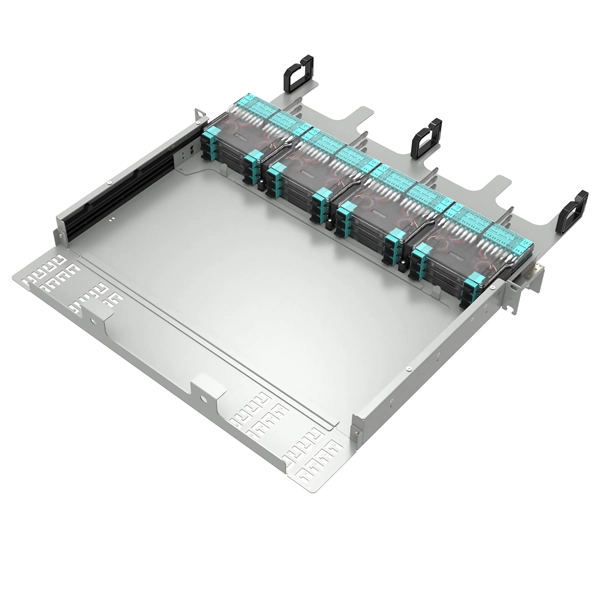
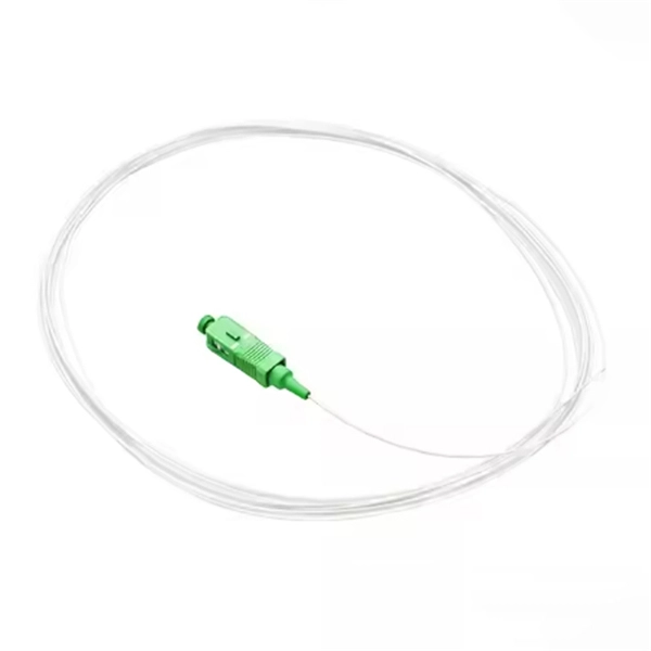
Product Features: Square protective box, suitable for skin cable and leather cable tight protection 6cm in length of skin heat shrink tube welding protection. A close connection between the leather cable and pigtail. Looking for specific info?. *In the era of high bandwidth, reliable fiber optic power equipment is particularly important. This handheld photometer can help check cable performance, calculate relative power loss, locate faults, and troubleshoot. *Measure the length of network cables, coaxial cables, and telephone cables. Able. Usually ships within 3 to 4 weeks Click here for details of availability. Able to test open, short, cross-connect, See more product details TABKER 4000667180167 3 x 2 x 1. Check each product page for other buying options. Price and other details may vary based on product size and color. Need help?. power across any given fiber. This document will serve as an overview of the major features and functions of the device and will ofer tips for trouble shooting com on issues in optical networks. If you are looking for a low cost device capable of saving and reporting take a look at the RP460 or. ments to the instrument's performance and functionality. The figures given in this manual ion of this manual to ensure the accuracy of its contents. However, should you have any questions or fi gistered users with a variety of information and services. Please allow us to serve you best by.
[PDF]

In this video, we'll show you how to connect an energy meter to a distribution board (DB) safely and efficiently. energy meter connection with distribution box How to Connect an Energy Meter to Your Distribution Box Easily Steps to Properly Connect Your Energy Meter to a Distribution Box. It plays a vital role in ensuring the safe and efficient distribution of electricity throughout the premises. What is the wire from the meter to the breaker box? Also. Always begin with disconnecting the main supply before accessing any enclosure containing distribution components. This prevents arc faults and ensures safety when modifying or inspecting current paths. This “meter to panel” wiring establishes the pathway for all incoming electrical power from the grid to the home. Its primary function is to safely and reliably. Distribution Board aslo know as “Panel Board”, “Switch & Fuse Board” or “Consumer Unit” is a box installed in the building containing on protective devices, such as circuit breaker, fuses, isolator, switches, RCDs and MCBs etc. The electric main supply (230V AC & 120V AC in US) is connected through. Changed Texas's reference diagram for the 3 wire network 120/208 Volt single phase self-contained Revised Figures 13, 14, 14b. Limited the meter location from pad mount transformer for PSO. Removed unistrut being listed as an alternative means for mounting the meter box. APCo and TX do not allow.
[PDF]
Explore 20 top manufacturers and suppliers of Optical Time-Domain Reflectometers in our comprehensive photonics buyers' guide. Importer and distributor of photonics components and subsystems for use in instrumentation. Optical time-domain reflectometers (OTDRs) are measurement instruments that inject optical pulses into a fiber and measure the returning light scattered by Rayleigh scattering or reflected by Fresnel reflections. Products include photomultiplier tubes, solid-state photodetectors, IR. Time-Domain Reflectometers (TDR) and Optical Time-Domain Reflectometers (OTDR) are essential tools used in telecommunications, fiber optics, and cable testing industries for analyzing the integrity of cables and pinpointing faults. Various time-domain reflectometers are available, intended for different uses and requirements. These are some of the reflections using a comparative TDR. Our catalog includes 106,303 manufacturers, 20,788 distributors and 94,584 service providers.
[PDF]

These networks rely on optical fibers, which are thin strands of glass or plastic that carry light signals. The ONU serves as the termination point of a fiber-optic network, converting the optical signals back into electrical signals for distribution to end-user devices. A GEPON system usually consists of an OLT (Optical Line Terminal) at the service provider's central office and multiple ONU (Optical Network Units) or ONT (Optical Network Terminals) close to the end user as optical splitters. In addition, the transmission between OLT and ONU/ONT adopts an optical. In the realm of Fiber-to-the-Home (FTTH) and other FTTx architectures, the Optical Network Unit (ONU) is a critical piece of customer-premises equipment (CPE). The primary function of an. ONU stands for Optical Network Unit. Think of it as. ONU (Optical Network Unit) plays a crucial role in modern telecommunications, enabling seamless connectivity and high-speed data transmission across fiber optic networks. As global demand for Fiber-to-the-Home (FTTH) expands, ONUs have become essential for delivering reliable broadband to homes. As an essential node in Passive Optical Networks (PON), the ONU not only handles the conversion between optical and electrical signals but also supports various services such as data, IPTV, and voice. This article will provide a detailed explanation of the working principles of ONUs and their.
[PDF]
The Aerial Cable Marker provides easy identification of your cables during maintenance or emergencies. The easy wraparound design eliminates the need for special tools and adhesives. Using decals on the 1 3/4″ extension will distinguish your cable from other aerial utility lines. All cable markers are BEAD and BABA compliant. Online shipping rates and pricing may differ from offline. Online prices. There are many ways to identify and mark assets which include ANSI Signs and Labels, E-Z Tags 1” Pole Markers, Fiber Optic Markers, Write-On Markers, and Wrap Around Markers. ANSI Signs and Labels – ANSI Signs and Labels follow the standards and guidance from the ANSI Z535 Standards. These. Check each product page for other buying options. Need help?. Quickly identify cables, fiber optic and CATV lines with ACP's UV-stabilized Hang Around Marker. The marker is thermoformed to create a permanent coil that will always return to a coiled position. Note: We recommend the standard flap sizes (see chart below) for outdoor environments. Missing, faded, or damaged markers result in considerable down-time for field repair personnel. Premax produces transmission line markers that are large, rugged, and identifiable from a considerable distance.
[PDF]

In this step-by-step guide, we will walk you through the process, ensuring that you can seamlessly connect your optical cable and enjoy a clear and uninterrupted audiovisual experience. Optical cables are becoming increasingly popular for transmitting high-quality. Optical audio cables can easily improve your TV's sound by connecting to external speakers. Learning how to connect an optical cable is easy, but there are a couple of gotchas that you should know. Here are the basics: Identify the optical output; if there's a protective plastic cap, remove it. The most common types are: The Toslink optical cable is a standard for transmitting digital audio signals. It uses a plastic or glass fiber to carry light signals from one. You can connect an older flat screen TV to ANY Stereo system, Surround Sound system, or Soundbar. This video shows you step by step how to make audio connections using an digital optical cable. You can use an optical connection even if your audio system does not have an optical socket, and by using. One of the easiest ways to achieve high-quality sound is to connect your TV to a home theater system or soundbar. Easily connect your optical audio cable to your TV! Follow our step-by-step guide for a hassle-free setup and enjoy crystal-clear sound. No wonder how to improve TV sound, right? When the sound is weak, for example, when using an analog sound source, then an optical audio cable possibly will be the.
[PDF]

Bit Error Rate (BER) is a critical performance metric in optical communications that measures the number of errors occurring in a transmitted data stream over a certain period. It is defined as the ratio of the number of bits received in error to the total number of bits transmitted. This ratio is most often expressed using scientific notation (e., 10⁻⁸. USI has industry-leading capabilities in high-speed signal integrity and power integrity (SI/PI) design, as well as advanced thermal simulation and optical simulation using Zemax. In addition, we have strong expertise in high-speed PCB design utilizing mSAP and substrate PCB technologies. USI also. Unlock AI-driven, actionable R&D insights for your next breakthrough. As optical links are increasingly used for high-speed data. Even a digital data transmission system is not totally error-free — statistical fluctuations related to noise influences cause a small percentage of the transmitted bits to be corrupted. The average fraction of incorrectly transmitted bits is called the bit error rate. Offers precise, cost-efficient optoelectronic signal and anomaly testing for high-speed transceivers. · Use control board and replaceable.
[PDF]
ONU, o Unidad de Red Óptica, se refiere al dispositivo terminal óptico dentro de una red de acceso de fibra. Proporciona a los usuarios múltiples interfaces de servicio, convirtiendo señales ópticas en señale.
[PDF]