
Sensitivity Test: Confirms that the protection works properly for internal defects in the protected zone. Inject primary current via one set of CTs, with one current flowing inward & the other outward. If the CTs are properly connected, there should be no operating current at the. A protective relay is basically an electrical device that detects a fault in a power system and initiates the operation of the circuit breaker to isolate the defective section or component from the rest of the system. In other words, the prime function of protective relays is the timely and. To conduct the tests effectively the following devices and equipment are required: Primary Injection Test Kit – for injecting large currents directly into CT circuits. Secondary Injection Test Kit – Simulates relay inputs with the controlled currents and voltages. It emphasizes selectivity, coordination, fault response, and system behavior rather than individual relay devices. This prevents damage to equipment, reduces downtime, and safeguards. This handbook covers the code of practice in protection circuitry including standard lead and device numbers, mode of connections at terminal strips, colour codes in multicore cables, dos and donts in execution. Its main purpose is to safeguard electrical equipment like transformers, generators, and transmission lines from damage due to.
[PDF]

Generator protection relays are devices that detect abnormal operating conditions and isolate the generator from the system to prevent damage. These relays act as the first line of defense and are installed with strict adherence to IEC Standard for Protection Relays. Protecting generators from different electrical, mechanical, and thermal stresses is known as generator protection. To safeguard machines from overloads and unusual circumstances, preventive measures are required. Faults are inevitable even with effective design, construction, and operation. Below is an overview of the different types of relays used in generator systems, their functions, and their specific applications. Electromagnetic relays use. Generator Protections are broadly classified into three types: Class A, B and C. Class A covers all electrical protections for faults within the generating unit in which generator field breaker, generator breaker and turbine should be tripped. What Are Generator Protection Relays? Generator protection. There are various protection relays and those are used for protection against a wide variety of conditions. The fundamental principles that are covered in this course are equally applicable to. IEEE C37. 2 defines the IEEE “numerical” function designation for all protective relay functions. This presentation primarily uses the designations from the Beckwith M-3425A relay, which in most cases follows IEEE C37.
[PDF]

Numerical relay are embedded with specialized digital signal processor (DSP) as the computational hardware. By using DSP as the relay's processor, the relay is capable of meeting the fundamental protective requirements such as reliability, sensitivity, selectivity and speed . Thus, various protective devices are used to protect the power system, of which digital signal processor (DSP) numerical relays are capable of significantly improve protection operations. Therefore. Manuals and User Guides for Samwha DSP DSP-VIP-PM Motor Protection. We have 1 Samwha DSP DSP-VIP-PM Motor Protection manual available for free PDF download: Manual Samwha dsp DSP-VIP-PM Motor Protection Pdf User Manuals. View online or download Samwha dsp DSP-VIP-PM Motor Protection Manual. Many of the new protection relays are microprocessor based and are generally referred to as numerical relays. This means that signals from transducers are sampled at fixed time intervals, digitally encoded, and processed by equipment which resembles a computer to derive relaying information, e.
[PDF]
In fiber optic circuit technology an optical fiber link is used for transferring digital or analogue data in the form light frequency through a cable which has a highly reflective central core. Internally, the optical fiber.
[PDF]
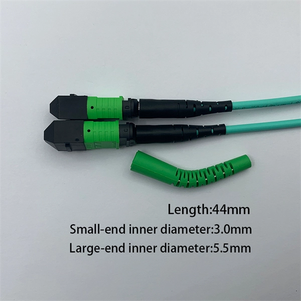
Figure 1 is a diagram of the basic construction of both loose-tube and tight-buffer fiber optic cable. An optical fiber cable is a complex structure designed to protect fragile glass fibers that transmit digital data using light signals. This advanced cabling solution allows fast, secure data transfer and telecom over long distances. Understanding the components within a fiber optic cable enables. A fiber optic cable consists of five basic components: the core, the cladding, the coating, the strengthening fibers, and the cable jacket. When searching for a fiber optic cable, we need to pay attention not only to the connectors, such as SC to ST fiber cable, LC to SC fiber patch cable, or SC to. Optical fibers are circular dielectric wave-guides used to contain and transmit light over short or long distances. They consist of three elements as shown in Figure 1: a central core, cladding and a protective coating. Understanding its internal structure is essential to appreciate how it functions efficiently in various applications, from telecommunications to medical devices. The core is the. 3,260 optical fiber structure illustrations, drawings, stickers and clip-art are available royalty-free for download. Multimode all-media self-supporting fiber optic cable structure isolated on white. More specifically, we can say that it is a waveguide that has the ability.
[PDF]

Distribution box The system diagram usually shows the electrical connection and configuration inside the distribution box in a graphical way, including busbars, circuit breakers, fuses, load devices and other elements. In practical applications, the corresponding system diagram can be drawn. A wiring diagram symbols chart is a visual representation of the various symbols used in electrical diagrams. It provides a quick and easy reference guide to understanding the meaning behind each symbol. These symbols can represent different electrical components, such as switches, resistors. Hey, in this article we are going to see the Single Phase Distribution Box Wiring Diagram and Connection Procedure. A distribution board or distribution box is where the main power supply is distributed to multiple loads. Understand its role in electrical systems and safety. It helps control and distribute electricity to different areas. Inside. In the world of electrical installations, the term DB box —short for Distribution Board box —refers to the central unit that distributes incoming electrical power to multiple outgoing circuits in a building. Whether you're powering up a residential home, a commercial office, or an industrial plant. Power distribution panel is used for utilization of equipment. A molded case circuit breaker are used which incomer supply is connected with LT panel and outgoing supply is connected width panel busbar.
[PDF]

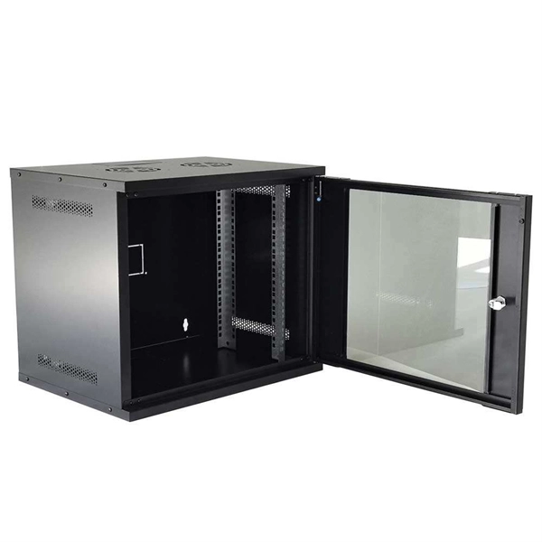
In this guide, you will learn how to interpret network diagrams like a pro, from symbols and scope to segmentation, dependencies, troubleshooting, and security clues. A rack elevation diagram is a visual representation of the equipment and components contained within a rack in a data center or server room. It provides a clear overview of the physical layout of the rack, including the placement and positioning of servers, switches, storage devices, and other. Learn how to read and interpret network diagrams effectively to troubleshoot, validate security, and plan network changes with confidence. Have you ever opened a network diagram and felt like you were staring at a subway map with no station names? That is a common problem, even for experienced IT. Network cabinet cabling describes the structured connection and arrangement of all IT components in a server rack. The aim is a secure, maintainable and scalable operation of the network environment. The amount. A standard operating procedure, or SOP, is a set of step-by-step instructions compiled by an organization to help workers carry out complex routine operations. Work instructions should be very detailed on "how" to accomplish a specific job, task or assignment. It helps teams understand network architecture, data flow, and dependencies, making it easier to design infrastructure, troubleshoot issues, and plan.
[PDF]
Thermal relays are the perfect solution for providing protection to motors which provides the most precise tripping for the electric motor during single phasing and overload. This article discusses an overview.
[PDF]
The original unstructured record data for the defect of the relay protection devices (RPDs) may contain problems influencing the data mining, and it is lack of quantitative evaluation. So the purpose of this.
[PDF]
Important transmission lines and generators have cubicles dedicated to protection, with many individual electromechanical devices, or one or two microprocessor relays.OverviewIn, a protective relay is a device designed to trip a when a is detected. The first protective relays were electromagnetic devices, relying on coils operating on moving par. Electromechanical protective relays operate by either, or. Unlike switching type electromechanical with fixed and usually ill-defined operating voltage thresholds.
[PDF]

Simple 3-phase distribution board wiring diagram for home use, showing safe connection of power supply, breakers, neutral, and earth for residential electrical systems. Hey, in this article we are going to see the Three (3) Phase Distribution Board Wiring Diagram and Connection Procedure. The three-phase distribution board is used to distribute power to the three-phase loads and circuits such as three-phase motors, three-phase machinery, three-phase to. A distribution board, also known as a DB box, is like the central hub of an electrical system. It contains multiple circuit breakers and connects various electrical circuits to ensure the safe flow of electricity throughout the building. Unlike single-phase systems, where power is distributed using. When it comes to understanding the basics of electricity and wiring, a wiring diagram of a three phase distribution board is indispensable. This diagram shows how electricity is distributed in a home or building and helps you identify which connections should be made when constructing, modifying or. Welcome to our channel! In this video, we'll walk you through the process of wiring a home distribution box with a detailed connection diagram. Whether you're an electrician or a DIY enthusiast, this guide will help you understand the basics of home electrical distribution. These setups typically provide 240V for most applications, but it's crucial to follow the proper configuration to prevent hazards.
[PDF]
A fiber coupler is a passive optical device that manages the flow of light signals within an optical network. It functions by dividing a single incoming light path into multiple outgoing paths, or by combining light from several input paths into a single output fiber. What are some common uses of fiber couplers in fiber optics, including fiber lasers? What are dichroic couplers and how are they used in fiber amplifiers? What is the principle of evanescent wave coupling? What factors influence the coupling strength and wavelength sensitivity in fiber couplers?. This tab provides a brief explanation of how we determine several key specifications for our 1x2 couplers. This capability is fundamental. Fiber optic coupler is one type of fiber optic component that allows for the redistribution of optical signals. It covers a wide range of fiber optic devices such as optical splitters, optical combiners, and optical couplers. A fiber optic coupler is a device that can distribute the optical signal. Fiber optic couplers are optical devices that connect three or more fiber ends, dividing one input between two or more outputs, or combining two or more inputs into one output. List the types of extrinsic and intrinsic coupling losses. Understand the degree to which fiber alignment and fiber mismatch problems increase system loss. Detail the score-and-break cleaving.
[PDF]
The equipment is used as a termination point for the feeder cable to connect with drop cable in FTTx communication network system. The fiber splicing, splitting, distribution can be done in this box, and meanwhile it provides solid protection and management for the FTTx network. PTE 24 U. 24-Port Fiber Optic Terminal Box is widely used in Italy in conjunction with the Optotec ROE Multi-Dwelling Unit (MDU) and PTE termination box. The cabinet. The HTB8067 24 Port Indoor Fiber Optic Distribution Box is designed for clean, efficient cross-connection between outdoor backbone cables and indoor subscriber fibers. Total. Tailored for FTTH in multi-dwelling units, serving as a floor-level transition for riser and horizontal cables. Provides storage for overlength and terminated fibers along with splicing capabilities. Suitable for indoor floor installations in residential or commercial buildings. Fiber optic cables, composed of ultra thin glass or plastic fibers that transmit data as light signals, are extremely fragile. Even minor physical stress, such. The 24 port NID can load LC or SC adapters and pigtails, 1x16 or 2x16 Optical PLC Splitter. This UV resistant shell is designed.
[PDF]
Residual current protection (RSD/RCCB/RCBO): Detects leakage current and cuts off power to reduce electric shock risk. Earthing connection: Ensures proper grounding to maintain safety and system stability. Many modern distribution boxes include a life-saving device called an Earth Leakage Circuit Breaker (ELCB) or Residual Current Device (RCD). It detects tiny imbalances in current that could be flowing through a person (electric shock) and cuts power in a fraction of a second. The Role of Material:. Metal Distribution Boxes: Made from steel or aluminum, these are used in places that require higher safety standards, such as fire-resistant buildings. Plastic Distribution Boxes: Constructed from materials like PVC or polycarbonate, these boxes are light and resist corrosion, making them suitable. These tools show where you can save electricity. Smart meters show detailed energy use. Monitors cut waste by improving power use. Efficient boxes reduce power loss in big buildings. It integrates power distribution, protection, and monitoring capabilities, and is responsible for distributing power to entire commercial or residential.
[PDF]
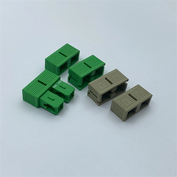
Fiber optic couplers are optical devices that connect three or more fiber ends, dividing one input between two or more outputs, or combining two or more inputs into one output. The device allows the transmission of light waves through multiple paths. These connectors combine the compact form factor of a standard duplex LC with a rugged, waterproof housing, delivering high-performance optical links that withstand rain, dust, temperature. Fiber optic adapters, also known as couplers, play a crucial role in fiber optic networks by providing a connection point between two fiber optic connectors. They enable seamless and reliable optical signal transmission between different fiber optic cables, connectors, or devices. In this tutorial. A fiber coupler is a passive optical device that manages the flow of light signals within an optical network. Directional 2 × 2 couplers (see Figure 1) are usually used for such purposes. This article explores the function, types, and applications of fiber.
[PDF]


