
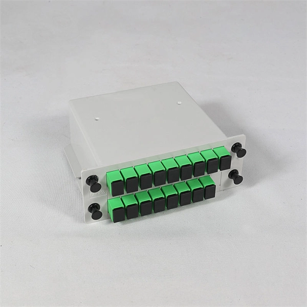
An Optical Splitter, also known as a beam splitter, is a passive optical device that divides a single input optical signal into two or more output signals. Conversely, it can also combine multiple signals into one. Knowing the difference between a splitter and an optical coupler helps you build better networks. You make your network work better when you pick the right device for each job. You can connect many users to one port with 1:n or 2:n splitters. By dividing a single optical signal from a central Optical Line Terminal (OLT) into multiple outputs for Optical Network Terminals (ONTs) at users' homes, splitters eliminate the need for dedicated fibers to each residence—slashing infrastructure costs while scaling network reach. This guide. In a Passive Optical Network (PON), a single optical fiber carries massive amounts of data using light. Signal Input: The fiber splitter receives the optical signal from the upstream network node and enters the splitter through the input fiber. Signal Distribution: Inside the splitter, according to the design structure and different. Splitters are passive optical devices that divide or combine optical signals, and they come in various types, including power splitters, uneven splitters, and wavelength-division multiplexing (WDM) splitters. Each type serves specific applications, enabling efficient use of optical infrastructure.
[PDF]

A ladder type cable tray tee is a fitting used to create a branch in a cable tray system, allowing cables to be routed in three directions. Its "T" shape provides a secure and efficient way to split cables from a main tray into two separate paths, ensuring organized and flexible. A cable tray tee and tee cover are components used in cable management systems to support and protect electrical and data cables. Here's a brief explanation of each:. Rigid steel cable tray tee fitting with zero tangent, safety bottom, and full accessory support. ventilation to heat producing cable such as power communication and other with the same or different width of the cable run. All fittings are available in sizes and types corresponding to the straight cable tray sections. These fitting are including: elbow, horizontal cross, vertical inside. NOTE : Equal or un equal tees can be supplied. When ordering state widths W1xW2xW3.. Office: 147/22 Nguyen Sy Sach Street, 15 Ward, Tân Binh Dist, HCMC,VN. Is it possible to connect 2 cabletrays with a "branch piece (left picture)" instead of a "tee (right picture)". The tee has 3 connectors, the branch piece only has 1 connector. I would like to ajust the "Type properties -> Fittings -> Tee" with the branch family, but can't get it accomplished.
[PDF]

Cable Trays* — Max two 24 in. (610 mm) wide by max 6 in. (151 mm) deep open-ladder cable tray with channel-shaped side rails formed of 0. 54 mm) thick aluminum or min 0. In practice, cable tray dimensions are a system of interrelated measurements —width, depth, length, and material thickness—that directly affect cable fill compliance, heat dissipation, structural loading, and long-term expandability. From an engineering standpoint, cable tray dimensions are not. Perforated Cable Tray System expertly constructed from high-grade stainless steel, offering exceptional durability and resistance to corrosion. With side height 100mm. A properly designed and installed cable tray system will provide. Studs — Wall framing to consist of wood studs or channel shaped steel studs. Wood studs to consist of nom 2 by 4 in. Additional studs shall be used to completely frame. Best Size: Here, deep trays (75mm to 150mm) are used since power cables are typically thick and heavy. Data cables, such as your Wi-Fi or computer ones, are extremely sensitive. They do not get hot; however, they do not like to hang or sag. In case a data cable folds in an excessive manner, the. ect the minimum bend ra-dius for cables as they exit the bottom of the cable tray. A rung spacing of 6 to 9 inches (150 to 230 mm) is preferable when the cable tray cont d for instrumentation and control applications that require additional protec eferred to support and protect numerous small.
[PDF]

This article provides a detailed technical comparison between fiber optic and copper cables, offering a clear perspective for engineers, network architects, and procurement managers. The core distinction between the two technologies lies in the physics of data. There are significant differences in performance between ADSS cables (all-dielectric self-supporting optical cables) and traditional optical cables, which are mainly reflected in the following aspects: 1. This type of fiber optic cable is designed to support its own weight without the need for additional support structures like messenger wires. The ADSS. There are several factors to assess when deciding which cable type is right for your application, including speed of connection for new customers, ease of changes and repairs, installer certification requirements, and the ability to expand the network over time. ADSS Fiber Optic Cables are a type of optical fiber cable designed specifically for. All-dielectric self-supporting (ADSS) cable is a type of optical fiber cable that is strong enough to support itself between structures without using conductive metal elements. It is used by electrical utility companies as a communications medium, installed along existing overhead transmission.
[PDF]

NPO (Near-Packaged Optics) is a transitional technology bridging traditional pluggable modules and CPO. It integrates the optical engine and GPU chip side-by-side on the same high-performance PCB or organic substrate, connected via ultra-short high-speed circuits. Its core concept is to remove digital processing units such as DSPs and CDRs from the module, constructing a purely analog "linear direct-drive" optical link. In the LPO architecture: The transmitter uses a high-linearity driver chip to directly drive the optical modulator, converting the. Near-packaged optics (NPO) helps send data faster. It puts the optical engine close to the switching chip. This makes things work better. NPO lets you upgrade easily. You do not have to redesign your whole system. It lowers energy costs. Among the emerging technologies, LPO (Linear Pluggable Optics), NPO (Near-Packaged Optics), and CPO (Co-Packaged Optics) represent three important stages in the evolution of next-generation data center optical networking. Understanding how these architectures differ is essential for designing. Traditional optical modules typically rely on DSPs (Digital Signal Processors) to handle signal equalization, retiming, and compensation, mitigating attenuation and distortion during transmission. They are not concepts at the same level, but rather.
[PDF]

FS optical line protection switch features 1+1 backup and less than 15 ms fast switch to the standby fiber link that ensures business uninterrupted when malfunction occurs. An optical protection switch is a critical component in fiber optic communication systems designed to safeguard optical signals and infrastructure from damage due to power surges, signal overloads, or system failures. These switches ensure signal integrity, minimize downtime, and enhance network. 1+1 Optical Line Protection System for Fiber Protection, Bi-directional Protection in Dual Fiber, LC/UPC, Pluggable Module OLP (Optical Line Protection) is a device used in pairs, one at each end of the optical signal to protect network transmission line. OLP products include fiber optical line protection switches, optical bypass switches, optical cross connection, multi-channel. The FOSW-1x1 or 1x2 optical switch is based on opto-mechanical technology with proven reliability. OSW-W1x2 optical switch is a high performance electro-optical device, with low insertion loss (typic. In optical communication network, OLP monitors optical power of optical fiber and standby.
[PDF]

Here at AFL we provide years of experience and excellent solutions for your hardware needs in both ADSS (All-Dielectric Self Supporting), OPGW (Optical Ground Wire) and SkyWrap cables. Please follow the links below for assistance in choosing your hardware. The aluminum Opti-LoopTM FOS for All Dielectric Self Support (ADSS) cable is available in 3 sizes. With more than one million units in service, Opti-Loop fiber storage systems lead the industry in quality and durability. All aluminum construction with continuous welds at crossbars and ends. Each. Also see our line of ADSS Fiber Optic Cable. © Copyright 2026 AFL. Our product experts are here to assist you. Get in touch with our team now. PLP transmission, distribution, substation, fiber optic, solar, and EV solutions protect and connect overhead electric power lines and communications networks. ADSS Anchor Tension Clamps are hardware fittings used to securely terminate and anchor ADSS fiber optic cables on poles or towers without damaging the cable. This is a type of self-supporting optical fiber cable that does not require any kind of support in distributing electricity from one point to another. As much as they may be independent, these cables are usually installed on poles and.
[PDF]

The wavelength of the 40G QSFP+ SR4 optical module is 4x850nm, while the 40G QSFP+ LR4 optical module adopts CWDM coarse wavelength division multiplexing technology, with four wavelengths of 1271nm, 1291nm, 1311nm, and 1331nm. The fiber type and connector are different. 40GBASE-ER4 is a long-reach 40GbE optical standard that delivers 40Gbps transmission over single-mode fiber up to 40km using QSFP+ transceiver. It achieves this reach by multiplexing four CWDM optical lanes into a duplex LC fiber interface, allowing long-distance connectivity without requiring. While 100G and 400G technologies continue to advance, 40G QSFP+ optical modules remain a mainstream, cost-effective solution for upgrading small to medium-sized data centers. It is commonly deployed in data centers, enterprise backbone networks, and metropolitan area networks where stable, high-speed transmission over extended distances is. In the deployment of 40G networks, the 40G QSFP+ optical module is one of the most widely used, defined by IEEE 802. The two basic interface specifications for QSFP+ optical modules are 40G BASE-SR4 and 40G BASE-LR4. In this blog, ETU-LINK will talk about. The QSFP+ module is designed for use in 40GBASE Ethernet throughput up to 10km, 30km or 40km over single mode fiber (SMF) using a wavelength of 1310nm via duplex LC connectors. This transceiver is compliant with QSFP+ MSA and IEEE 802. Digital diagnostics functions are also available.
[PDF]

This section provides an overview for optical power meters as well as their applications and principles. Our list of suppliers for that category contains 69 suppliers. Understand the Technical Background To support your technical evaluation, this section includes links to authoritative encyclopedia articles for in-depth verification of the underlying physics, technical issues and techniques. Market Forecast By Type (Thermal Detectors, Photo Detectors), By Instrument/Product Type (Benchtop Meter, Portable Meter, Virtual Meter, Optical Wavelength, Hand-Held Meter, Others), By Detector Type (InGaAs (Indium Gallium Arsenide), Germanium, Silicon, Others), By Power Range (High, Medium, Low). This section provides an overview for optical power meters as well as their applications and principles. Here are the top-ranked optical power meter companies as of May, 2026: 1. Novanta. Photon Systems, Inc. designs, develops, manufactures and markets deep ultraviolet lasers and incoherent sources, instruments based on these sources, and optical and electro-optical accessories for a broad range of applications primarily within the. All of EXFO's modular (IQS line) and benchtop power meters are built for top performance and pinpoint accuracy, and the various models offer a mixture of features and specifications to suit various test setups. Fast, accurate, flexible power. © Copyright© Santec Holdings Corporation.
[PDF]

Optical Modules Market Segments - by Product Type (Transceivers, Receivers, Transmitters, Amplifiers, and Others), Application (Data Centers, Telecommunication, Enterprise Networking, and Others), Distribution Channel (Online Stores, Direct Sales, Indirect Sales . Optical Modules Market Segments - by Product Type (Transceivers, Receivers, Transmitters, Amplifiers, and Others), Application (Data Centers, Telecommunication, Enterprise Networking, and Others), Distribution Channel (Online Stores, Direct Sales, Indirect Sales . Data centers will keep dominating optical module demand as AI and cloud drive revenue growth through 2030. Optical module demand is being pulled in two directions at once, faster bandwidth for dense networks and tighter constraints on power, security, and lead times. 8% during the forecast period 2025-2031. The potential shifts in the 2025 U. tariff framework pose substantial volatility. The Optical Module Market size was estimated at USD 26. 53 billion in 2025 and expected to reach USD 30. The accelerating explosion of global data traffic has thrust optical modules into the heart of modern communications.
[PDF]
Cambodia Fibre Optic Communication Networks Co., Ltd (CFOCN) has requested the Ministry of Public Works and Transport (MPWT) for approval to undertake a project involving the drilling and installation of new fibre optic cables across Cambodia's nine major provinces. This request was discussed during a meeting. Established since 2022, and obtained a license from Telecommunication Regulator of Cambodia (TRC) Who We Are? Established in 2022, and obtained a license from the Telecommunication Regulator of Cambodia (TRC). – Cambodia Licensed Provider for Operation and Provision of Telecommunications Cable. Telcotech is Cambodia's trusted choice of Telecommunication Infrastructure and Associated Services Provider. With a 30,000-kilometer-long. The project company comprises investment of two fiber optic telecommunication networks which are the undersea fiber optic cable Asia-Africa-Europe 1 (AAE-1) and the land cable network (the 'Project'), as detailed in the following report. The project will be developed by (Cambodia) Fiber Optic. Phnom Penh (FN), Aug. 14 – Telcotech is one of the market leaders for infrastructure in Cambodia, subsea cable and also connectivity in the region, announced the cooperation with Huawei building Cambodia's first nationwide next generation transport network. It is understood that the network will.
[PDF]

Precast concrete trench systems provide protection and easy access to power, communication, fiber optic, control, and signal wires and cables. Engineered precast trench is used in the power, utility, and transportation industries and can also be used in conjunction with catch basins, inlets, and. Completing Outside Cable Plant Installation. Underground cables are pulled in conduit that is buried underground, usually 1-1. 2 meters (3-4 feet) deep to reduce the likelihood of accidentally being dug up. In extreme cold climates, cables may need to be buried at greater depths where there. THE SOLID APPROACH TO TRENCHING. Made of a unique, patented. Trenwa is the original manufacturer of precast concrete trench and offers the broadest line of proven trench systems. Trusted by Industry Leaders: Trenwa has been a go-to partner for North American infrastructure projects for over for over 60 years. Request a quote today to see how our products can. Waskey's Precast Cable Trench System offers a durable, customizable solution for protecting and organizing critical infrastructure. If you need any help, be sure to reach out. Precast Concrete Trench for underground utility purposes. Primarily used for enclosure of electrical, communication, power cables, and piping.
[PDF]

The QSFP28-100G-SR4 is a transceiver module designed for 100m optical communication applications. The design is compliant to 100GbASE-SR4 of the IEEE 802. 3-2012 Clause 88 standard IEEE 802. 100GBASE QSFP Active Optical Cable, 10m. 100GBASE QSFP Active. Each type provides information about the production during the forecast period of 2016 to 2027. Understanding the segments helps in identifying the importance of different factors that aid the market. TE SEACON is an industry leader in the design and manufacturing of underwater and subsea connectors, providing a comprehensive range of over 2,500 high-quality electrical and fiber optic connectors. The module converts 4 inputs. Global 100G Optical Transceivers Market Size By Product Type (Transceiver Modules, Active Optical Cables (AOCs)), By Interface Type (LC Interface, MPO Interface), By Application (Data Center, Telecommunication), By Transmission Distance (Short Range (up to 150m), Medium Range (up to 10km)), By Data. Modern data centers rely on high-speed optical links, and 100G optical transceiver modules (especially the QSFP28 form factor) are now foundational for this connectivity. 100G transceivers convert electrical signals to laser light over fiber, enabling top-of-rack switches to connect to aggregation.
[PDF]

Highly compact electro-optical modulators have been demonstrated in compound semiconductors. However, in silicon photonics, electro-optical modulation has been demonstrated only in large structures, and is therefore inappropriate for effective on-chip integration.OverviewAn is an optical device which is used to modulate a beam of light with a perturbation device. It is. An electro-optic modulator is a device which can be used for controlling the power, phase or polarization of a laser beam with an electrical control signal. It typically contains one or two, and possibl. Acousto-optic modulators are used to vary and control laser beam intensity. A Bragg configuration gives a single first order output beam, whose intensity is directly linked to the power of RF control signal. The rise ti. A dc magnetic field Hdc is applied perpendicular to the light propagation direction to produce a single domain, transverse directed 4~Ms. The rf modulation field Hrf, applied by means of a coil along t.
[PDF]
Fiber optic cables have revolutionized the way we transmit data, offering greatly improved speed and reliability compared to traditional copper cables. These cables use light to carry information, resulting in faster and more efficient communication. A TOSLINK optical fiber cable with a clear jacket. A fiber-optic cable, also known as an optical-fiber cable, is an assembly similar to an electrical cable but containing one or more optical fibers that are used to carry. What is DSL internet? Obsolete in most populated areas, DSL delivers internet using traditional telephone lines. It's different from the old-school dial-up of yesteryear, as you can use the internet and your landline at the same time, but it's still one of the older technologies out there. The process relies on a principle called Total Internal Reflection. What is Fiber Optic Cable? A Fiber Optic Cable is used to transmit data through fibers (threads) or plastic (glass). This pack of glass which is within sorts of threads transmits modulated messages along sunshine waves. There are many advantages of using these cables over other kinds of. Fiber-optic cables on cable drums are versatile. They are used wherever a glass fiber connection is temporarily required. For any kind of events, e. Trade fairs, sports events, conferences, filmed productions, etc. High-Speed Transmission: Fiber optics use light.
[PDF]