The beam splitter is one of the important elements in optical waveguide circuits. To improve the performance of an optofluidic beam splitter, a microchannel including a two-stage main channel with divergent side walls and two pairs of inlet channels is proposed. Besides, the height of the inlets. M. Oulad Haddar; Improvement of optical characteristics of silicon based 1×3 beam splitter with photonic crystal waveguide. 20 January 2022; 2440 (1): 020001. 0075004 In this work, we propose a new structure of 1×3. In the second step of this work we propose an optimization of the conventional splitter design leading to suppression of the asymmetric splitting ratio to one-third of its initial value and to the improvement of the losses by nearly 2 dB. In addition, 50% size reduction of the designed structure. d for the power splitting ratios are vital for the adaptive optical networks and photonic computing. Conventional mechanisms such as thermo-optic, free-carrier, or mechanical tuning are usually volatile and require continuous p wer, limiting their suitability for low-frequency and low. Optical and Quantum Electronics This paper aims to study the design, simulation, and optimization of low-loss Y-branch passive optical splitters up to 64 output ports for telecommunication applications. For a waveguide channel profile, the standard material silica-on-silicon is used.
[PDF]

Cable Trays* — Max two 24 in. (610 mm) wide by max 6 in. (151 mm) deep open-ladder cable tray with channel-shaped side rails formed of 0. 54 mm) thick aluminum or min 0. In practice, cable tray dimensions are a system of interrelated measurements —width, depth, length, and material thickness—that directly affect cable fill compliance, heat dissipation, structural loading, and long-term expandability. From an engineering standpoint, cable tray dimensions are not. Perforated Cable Tray System expertly constructed from high-grade stainless steel, offering exceptional durability and resistance to corrosion. With side height 100mm. A properly designed and installed cable tray system will provide. Studs — Wall framing to consist of wood studs or channel shaped steel studs. Wood studs to consist of nom 2 by 4 in. Additional studs shall be used to completely frame. Best Size: Here, deep trays (75mm to 150mm) are used since power cables are typically thick and heavy. Data cables, such as your Wi-Fi or computer ones, are extremely sensitive. They do not get hot; however, they do not like to hang or sag. In case a data cable folds in an excessive manner, the. ect the minimum bend ra-dius for cables as they exit the bottom of the cable tray. A rung spacing of 6 to 9 inches (150 to 230 mm) is preferable when the cable tray cont d for instrumentation and control applications that require additional protec eferred to support and protect numerous small.
[PDF]

A ladder type cable tray tee is a fitting used to create a branch in a cable tray system, allowing cables to be routed in three directions. Its "T" shape provides a secure and efficient way to split cables from a main tray into two separate paths, ensuring organized and flexible. A cable tray tee and tee cover are components used in cable management systems to support and protect electrical and data cables. Here's a brief explanation of each:. Rigid steel cable tray tee fitting with zero tangent, safety bottom, and full accessory support. ventilation to heat producing cable such as power communication and other with the same or different width of the cable run. All fittings are available in sizes and types corresponding to the straight cable tray sections. These fitting are including: elbow, horizontal cross, vertical inside. NOTE : Equal or un equal tees can be supplied. When ordering state widths W1xW2xW3.. Office: 147/22 Nguyen Sy Sach Street, 15 Ward, Tân Binh Dist, HCMC,VN. Is it possible to connect 2 cabletrays with a "branch piece (left picture)" instead of a "tee (right picture)". The tee has 3 connectors, the branch piece only has 1 connector. I would like to ajust the "Type properties -> Fittings -> Tee" with the branch family, but can't get it accomplished.
[PDF]

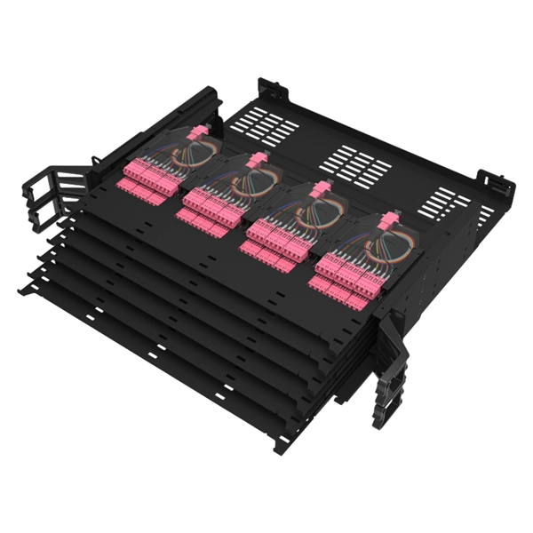
An Optical Splitter, also known as a beam splitter, is a passive optical device that divides a single input optical signal into two or more output signals. Conversely, it can also combine multiple signals into one. Knowing the difference between a splitter and an optical coupler helps you build better networks. You make your network work better when you pick the right device for each job. You can connect many users to one port with 1:n or 2:n splitters. By dividing a single optical signal from a central Optical Line Terminal (OLT) into multiple outputs for Optical Network Terminals (ONTs) at users' homes, splitters eliminate the need for dedicated fibers to each residence—slashing infrastructure costs while scaling network reach. This guide. In a Passive Optical Network (PON), a single optical fiber carries massive amounts of data using light. Signal Input: The fiber splitter receives the optical signal from the upstream network node and enters the splitter through the input fiber. Signal Distribution: Inside the splitter, according to the design structure and different. Splitters are passive optical devices that divide or combine optical signals, and they come in various types, including power splitters, uneven splitters, and wavelength-division multiplexing (WDM) splitters. Each type serves specific applications, enabling efficient use of optical infrastructure.
[PDF]
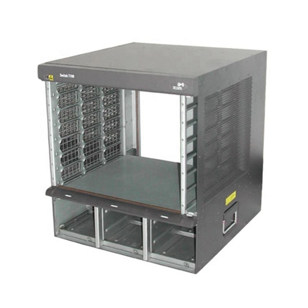
Here you can download the program for the configuration of our electrical cabinets. Written by Schneider Electric's most talented electrical distribution experts, the Electrical Installation Guide is written for professionals who design, install, inspect, and maintain low-voltage electrical installations in compliance with the standards published by the International. Perhaps you need to minimise heat losses to air in a facility without air-conditioning? Many of our most popular DC and AC power systems can be built into IP54 cabinets. An IP54 level of Ingress Protection provides a high level of protection against non-conductive airborne pollutants. Used to house electrical or electronic switchgear, control gear and equipment. The PDU series is designed to meet the needs of power distribution units of telecom access sites. It comes with an integrated controller that enables customer to read tenant-wise energy statistics as well as to extend the remote monitoring access. It is flexible enough to mount in the different. This Electrical Installation Wiki is a collaborative platform, brought to you by Schneider Electric: our experts are continuously improving its content, collaboration is also open to all. DC power is typically used in Data Centres and telecom facilities as it has several benefits. Firstly, DC power can be more efficient than AC power systems as the need for AC to DC conversion is.
[PDF]