5 inch CETC Optic fiber OTDR AV6418,Fiber optic test tester,1310/1550nm,45/43dB large dynamic range,built in Optic power meter and VFL Description: AV6418 OTDR mainly used to measure the physical characteristics of optical fiber under test,such as the length,the transmission loss. 6. 5-inch display offers an event blind zone of 1 m and operates with locater This product is already in your quote request list. Measuring Measuring loss (dB) in the range between 800nm – 1700nm. Power AC/DC adapter; Input:100V~240V, 50/60Hz. Polarization extinction ratio (PER) is a measure of the degree to which light is confined in a principal linear polarization mode. It is defined as the ratio of the power in the principal polarization mode to the power in the orthogonal polarization mode after propagation through a device or. The ERM2xx Extinction Ratio Meters measure the polarization extinction ratio (PER) and the polarization angle of polarization-maintaining (PM) fibers. It features unmatched low cost, all wavelength options, a large dynamic range, and high resolution. The design adds a rotary polarizer to an optical power meter.
[PDF]

In its most common form, a cube, a beam splitter is made from two triangular glass prisms which are glued together at their base using polyester, epoxy, or urethane-based adhesives. (Before these synthetic resins, natural ones were used, e. ). A beam splitter or beamsplitter is an optical device that splits a beam of light into a transmitted and a reflected beam. It is a crucial part of many optical experimental and measurement systems, such as interferometers, also finding widespread application in fibre optic telecommunications. In its. 📦 For purchasing, use the RP Photonics Buyer's Guide for beam splitters. It provides an expert-curated supplier directory, buyer-focused technical background information, and structured selection criteria to support professional procurement decisions. Light from an input fiber is first collimated, then sent through a beam splitting optic to divide it into two. The resultant output beams are then focused back into the output fibers. Note that jT j2 is the transmitted intensity. Similarly, E2 ! RE3 + T E4. The transformation matrix is then given by The elements of the beam splitter transformation matrix B are determined using the.
[PDF]

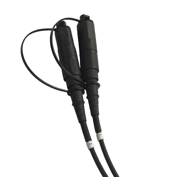
An SC/APC fiber optic adapter is a passive mechanical interface used to join two SC connectors that have angled physical contact (APC) ferrules, typically polished at 8°. Fiber couplers belong to the basic components of many fiber-optic setups. Note that the term fiber coupler is used with two different meanings: It can be an optical fiber device with one or more input fibers and one or more output fibers. It covers a wide range of fiber optic devices such as optical splitters, optical combiners, and optical couplers. A fiber optic coupler is a device that can distribute the optical signal. This small, inexpensive component is critical for aligning and mating two SC/APC connectors while preserving low insertion loss and ultra‑high return loss performance. Its core function is to distribute (split) or combine (combine) optical power while maintaining the spectral composition of the signal. The device allows the transmission of light waves through multiple paths. It functions by dividing a single incoming light path into multiple outgoing paths, or by combining light from several input paths into a single output fiber. This capability is fundamental.
[PDF]

Fusion splicing is the process of fusing or welding two fibers together usually by an electric arc. Fusion splicing is the most widely used method of splicing as it provides for the lowest loss and least reflectance, as well as providing the strongest and most reliable joint between. This guide reveals the secrets to fusion splicing with little fluff—just proven, straightforward techniques refined from years of work in the field. The goal is to fuse the two fibers together in such a way that light passing through the fibers is not scattered or reflected back by the splice, and so that the splice and the region surrounding it are almost as strong as the. A fusion splicer is a specialized tool used in fiber optic networks to join two fiber optic cables together permanently. This process creates a strong and reliable connection that can withstand. Splicing fiber optic cable is an extremely important phase for making dependable, high-speed communication infrastructures. Fusion splicing stands out as a superior technique for joining optical fibers, offering a seamless, low-loss connection that is crucial for reliable fiber optic networks. Let's explore the fundamentals of mechanical and fusion.
[PDF]
Answer: The current transfer ratio (CTR) is an important parameter in optocoupler selection. The gain of an optocoupler is expressed as the Current Transfer Ratio (CTR). It is defined as the ratio of the phototransistor output current (Ic) to the LED input current (If), expressed as. The current transfer ratio is a parameter similar to the DC current amplification ratio of a transistor (h FE) and is expressed as a percentage indicating the ratio of the output current (I C) to the input current (I F). The CTR has the following characteristics and is therefore as important as the. An optocoupler, also known as photocoupler or opto-isolator, is a device which can transfer an electrical signal across two galvanically-isolated circuits by way of optical coupling. Transferring signals over a light. As I understand the optocoupler current transfer ratio, CTR is like the hfe of a transistor. I can't understand if the CTR is or isn't a critical value and for what applications is it used in. Optocouplers contain both a light-emitting diode (LED) and a photo detector. The current transfer ratio. The current transfer ratio (CTR) refers to the ratio of the collector current at the output side I c to the input current passed to the LED at the input side I F expressed as a percentage. It is defined by the following formula.
[PDF]
The 3R A3140 AA serves as a fully compatible, drop-in replacement for the HCPL-3140, featuring matched performance metrics including propagation delay, CMTI, and output current, ensuring dependable real-world implementation in industrial and automation settings. The HCPL-3140/HCPL-0314 family of gate driver optocouplers consists of an GaAsP LED optically coupled to an integrated circuit with a power output stage. These optocouplers are ideally suited for driving power IGBTs and MOSFETs used in motor control inverter applications. The high operating voltage range of the. 0. Here you can find various types and values of electronic parts from the world's leading manufacturers. The HCPL-3140/A3140 components of Jotrin Electronics are carefully chosen, undergo stringent. The HCPL-3140-000E is a 0.
[PDF]

In this tutorial, I will show you how you can connect the Optocoupler to Arduino, read the data as Analog or Digital, and if necessary convert the analog values to digital, and how to reduce noise from the sensor. The Infrared Slotted Optical Optocoupler Module is a device that uses infrared light to transmit signals between two electrically isolated circuits. It consists of an infrared emitter (LED) and a photodetector (phototransistor) housed in a slotted enclosure. When an object passes through the slot. Slotted Optocouplers (Photo Interrupters) are very useful sensors, often included in Arduino projects to detect position of moving objects, measure speed of rotation, or linear motion, frequency of events, and many others. They are easy to use, but it is important to understand how they work, so. This tutorial is a comprehensive, practical guide to the Speed Sensor / Tacho Sensor (Slot-Type Optocoupler) (Leobot Product #245). Moreover, a simple application is programmed that shows how to wire and how to program an Arduino when working with the module. In this tutorial, the module is used as an “digital input board”. If you want to use the. In this project, I will talk about Phototransistor Optical Interrupter Switches (Opto Coupler) Module, how this module works and helps in determining the speed of a rotating object and finally I will show you how to Interface Optical Interrupter Switch Sensor with Arduino and measure the speed of a.
[PDF]