Although fiber optic networks present many advantages, there are also some disadvantages to take into consideration. These include physical damage, cost considerations, structure, and the possibility of a “fiber fuse”. By the early 1990's, as the internet was becoming popular in the public realm, fiber optic cabling started to be laid around the world. There was a big push to wire the world in order to. Optical fiber is a type of medium used for data communication or data transmission with the help of light pulses. Optical fiber is a hair-thin flexible stand made up of glass. It is capable of transmitting optical signals from one point to another over long distances. These days, optical fibers are. Fiber optic transmission has become the cornerstone of high-capacity communication networks, powering residential broadband, hyperscale data centers, 5G, IoT ecosystems, and global long-haul infrastructure. Additionally, fiber optic cables are delicate and require careful handling and installation. Electromagnetic interference (EMI) is a disturbance caused by electromagnetic radiation from an. There are many advantages of using these cables over other kinds of communication cables, like the bandwidth of these cables is high, and they are less vulnerable than metal cables.
[PDF]
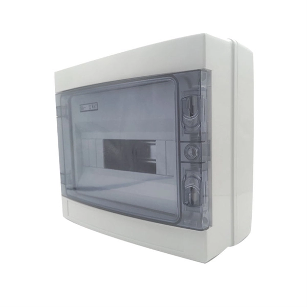
Advantages: Lightweight and easy to install. Excellent corrosion resistance and electrical insulation. Versatile design options to meet various requirements. Terminal boxes are essential components used for connecting electrical circuits, and the choice of materials significantly impacts the product's overall performance, safety, and lifespan. Below is a detailed analysis of commonly used materials for terminal boxes, along with their advantages and. ve Neutral Point Clamped). The reader will gain insight into elementary thoughts of how these 3L devices work, where advant ges and disadvantages are. Some hints concerning the layout/setup of 3L modules are given as well. However, the information given is not exhaustive and the responsibility for. Explore LCC technology—a key driver for the miniaturization and performance enhancement of modern electronic devices. Learn which is better for your electrical projects based on durability, safety, and cost. It's easy to overlook the small details when working on electrical projects. In many cases, there are several correct options, each with advantages, disadvantages, and costs to consider. Regardless of which box you select, a key factor. The fiber terminal box facilitates easy fixing, splicing, and mechanical protection of the fiber optic cables. With its user-friendly design and removable components, it simplifies troubleshooting tasks and reduces operational costs.
[PDF]
This article will deeply explore the unique charm of optical circulators from five aspects: the forefront of technological innovation, efficient cyclic transmission, wide application fields, excellent and stable performance, and future development prospects. Frontier of. An Optical Circulator is a non-reciprocal device that routes light from one port to the next, in a unidirectional manner. This unique device has broad applications in many fields, from optical telecommunications to fiber-optic sensor systems. They are crucial components in modern optics and photonics, enabling the efficient routing of optical signals. The basic principle of an optical. The evolution of optical circulators can be traced back to the advancements in fiber optics technology during the late 20th century, which necessitated the development of devices capable of managing complex light pathways. They are technically related to Faraday isolators, and on a broader scale similar to electronic circulators.
[PDF]
Facility location affects data center interconnection more than you might expect. High-performance interconnects and access to quality networks are two of the most vital considerations when selecting a colocation provider. However, without a strategic location, these benefits. Data center interconnect (DCI) is private network connectivity between multiple data center facilities that lets you treat geographically separated infrastructure as a unified environment. Instead of routing traffic between sites over the public internet, DCI uses dedicated circuits that provide. Interconnection is an over-arching term that refers to many different physical and virtual connections companies can select to exchange data, provide business continuity and customer services, and address specific business objectives. Interconnection in colocation data centers are vital for fast. Following are some of the drawbacks or limitations of data centers. Limited Local Control: Companies outsourcing to data centers have less direct control over their infrastructure because the hardware and support staff are located remotely. Data center facilities can work together by sharing resources and passing workloads between one another. This interconnection is typically achieved through high-capacity interfaces, including dedicated private lines, dark fiber, Ethernet, and internet-based connections. With DCI, SPs can host critical.
[PDF]
When deploying fiber optics in the field, telecommunications companies need ways to safely and efficiently store and terminate cables. As many technicians know, having the right fiber optic patch and splic.
[PDF]
Despite its numerous advantages, the use of InP in high-speed optical devices does come with challenges. The production process for InP can be complex and costly, which may limit its widespread adoption. Here are some key properties of Indium Phosphide (InP): Here are the key advantages of using Indium Phosphide: Superior Electron Velocity: InP boasts a much higher electron velocity compared to silicon (Si) and gallium arsenide (GaAs), approximately 5 times greater. Direct Band Gap: This property. Indium phosphide is a photonic integrated circuit (PIC) material suited for active functionalities. Beyond passive light routing, it can generate, amplify and detect light. Read on this page to learn more about indium phosphide characteristics, applications, and its comparison to other PIC. Indium Phosphide (InP), a duo-semiconductor born from the union of indium and phosphorus, has been thrust into prominence within the optoelectronics arena. Indium phosphide (InP) diodes are emerging as a promising semiconductor material for optoelectronics applications due to their. Abstract—A summary of photonic integrated circuit (PIC) platforms is provided with emphasis on indium phosphide (InP). Examples of InP PICs were fabricated and characterized for free space laser communications, Lidar, and microwave photonics. A novel high-performance hybrid integration technique.
[PDF]

Recommendation ITU-T L. 12 specifies splices of single-mode and multimode optical fibres. It describes suitable procedures for splicing that should be carefully followed in order to obtain reliable splices between single optical fibres or ribbons. Typical applications of these methods include aerial, buried, and underground splices. (2) American National Standard Institute/National Fire Protection Association (ANSI/NFPA) 70, 1993. § 1755. 370 - RUS specification for seven wire galvanized steel strand. 400 - RUS standard for. ation or liability to users of this publication. Existence of a standard shall not preclude any member or nonmember of NECA or FOA from specifying or using alternate construc Code (NEC) in effect at the time of publication. Because they are quality standards, NEIS® may in some instanc s go beyond. RUS standard for splicing copper and fiber optic cables. (FOA) was founded in 1995 to help develop the workforce to build the fiber optic networks to support a rapid expansion in communications and the Internet. The charter of the FOA was to promote professionalism in fiber optics through education, certification, and.
[PDF]
stands at the forefront of innovation with its pioneering tunable fiber Bragg grating technology. Our unwavering dedication lies in crafting state-of-the-art tunable fiber optic devices and systems with diverse applications. We specialize in custom fabrication of fiber optical gratings (FBG) across wavelengths from 400 nm to 2000 nm, tailored to precise customer specifications. Using high-power laser irradiation, we permanently modify the refractive index of the fiber core, delivering FBGs with low optical loss and. Optical Gratings are optical components that consist of a periodic structure of parallel slits or grooves etched or ruled onto a substrate material. The leading manufacturers of Gratings are listed below. Narrow down on the list of companies based on their location and capabilities. Products include phase masks, fiber optics based sensor and system, partial discharge and twin grating cavity sensors. Gould Fiber Optics is estimated to have 50-99 employees. Our patented fiber. TECHNICA focuses on Fiber Bragg Gratings (FBG) based products. Implementing our Mission we deliver the highest quality, most reliable, and. Explore 16 top manufacturers and suppliers of Fiber Bragg Gratings in our comprehensive photonics buyers' guide. A fiber Bragg grating is a type of optical filter that is inscribed or "written" into the core of an optical fiber. It consists of a periodic modulation of the refractive index along the.
[PDF]

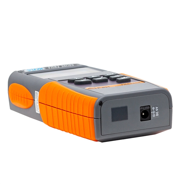
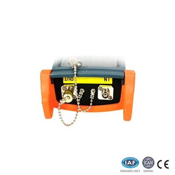
To use a power meter for fiber optic testing, always clean connectors first with lint-free wipes or click-to-clean tools. Select the correct wavelength and set your reference. You measure optical power in dBm or insertion loss in dB. Consistent procedures ensure accuracy. Verify light travels from. The most basic fiber optic measurement is optical power from the end of a fiber. This measurement is the basis for loss measurements as well as the power from a source or presented at a receiver. Typically both transmitters and receivers have receptacles for fiber optic connectors, so measuring the. An optical power meter measures the strength of light traveling through a fiber optic cable, giving you a reading in dBm (decibels relative to one milliwatt). This article will guide you through the methods, instruments, and key considerations for measuring fiber. Fiber optic cabling is the high-performance core of today's datacom networks. As network speeds and bandwidth demands increase, fiber performance requirements have become more stringent. Fiber testing is more important than ever. An OPM uses a photodiode to generate an electrical current proportional to optical power.
[PDF]

This practical file details experiments conducted in Optical Fiber Communication, covering modulation techniques, system components, and performance analysis. An optical fiber is a glass or plastic fiber designed to guide light along its length, widely used in fiber-optic communication, which permits transmission over longer distances and at higher data rates than other forms of communications. Fiber-optic communication is a method of transmitting. Availability of plastic optical fiber (POF) The plastic optical fiber used in some of these experiments is available for science distributors. It is a 1000micron (1mm) POF available from several suppliers. FOA has samples available at no cost for teachers at schools in the US. Key experiments include amplitude modulation, frequency modulation, and pulse width modulation, aimed at understanding fiber optic systems. This document summarizes 10 experiments on optical fiber communication: 1. Studying a 650mm fiber optic analog link and the relationship between input and received signals. Optical fiber communication Laboratory Optical fiber communication Laboratory List of Experiments: 1. To set up a analog optical fiber link 2. To measure the characteristics of LED and LASER 5. Tech curriculum designed to provide a comprehensive understanding of optical fiber communication systems. This lab offers an immersive, web-based simulator that enables you to explore and experiment with key concepts in optical.
[PDF]
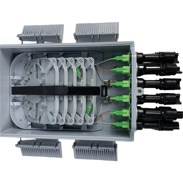
A fiber optic termination box is an enclosure designed to terminate incoming optical fiber cables and distribute optical signals to drop cables or patch cords. It integrates fiber splicing, adapter management, and cable protection in one compact unit. It is widely deployed in FTTH, FTTB, and other access networks to ensure stable signal transmission from backbone cables to end. ■ What is a Fiber Access Terminal (FAT)? A Fiber Access Terminal (FAT), also known as a Fiber Access Terminal Box (ATB) or Fiber Distribution Terminal (FDT), is a key component found in optimized fiber optic access networks for FTTH implementations. It acts like the "central nervous system". Fiber termination boxes play a vital role in ensuring efficient and reliable fiber management in FTTH applications. By understanding the components, types, and differences between various fiber management devices, businesses can make informed decisions when deploying and maintaining their fiber. But what exactly is the purpose of a fiber optic terminal box, and why is it so crucial in the realm of optical communication? First and foremost, a fiber optic terminal box serves as a robust protective shield for fiber optic cables and their delicate connections. It offers higher reliability and more flexible deployment and configuration than traditional terminal boxes. It is usually installed on the wall in the user's room or on the rack in the telecom room, and.
[PDF]

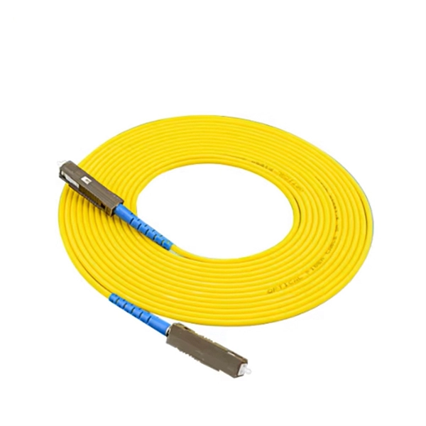
A8: Yes, multimode fiber optic cable can support high-speed data transmission depending on the fiber type and network equipment used. Multimode fiber (MMF) is an optical fiber designed to carry multiple light propagation paths—or modes—simultaneously. This is made possible by its relatively large core diameter, typically 50 or 62. 5 microns, compared to the ~9-micron core in single-mode fiber. The wider core accepts light from. Multi-mode optical fiber is a type of optical fiber mostly used for communication over short distances, such as within a building or on a campus. Multi-mode links can be used for data rates up to 800 Gbit/s. Multi-mode fiber has a fairly large core diameter that enables multiple light modes to be. In the realm of telecommunications and networking, multimode fiber optic cable plays a crucial role in efficiently transmitting data over short to medium distances. This guide aims to provide a concise understanding of multimode fiber optic cable and its applications. These fiber cables are structurally designed to transmit several light signals simultaneously, each of which is directed. Unlike copper cables, which rely on electrical signals, fiber optics use pulses of light to transmit data—offering unmatched bandwidth, low interference, and long-distance capabilities. But not all fiber cables are created equal: multimode (MM) and single mode (SM) fibers are the two primary types.
[PDF]

Optical Fiber Communication (OFC) revolutionizes modern telecommunications, enabling rapid data transfer across long distances with minimal signal loss. This comprehensive review explores OFC's historical evolution, core principles, components, and versatile applications. It traces OFC's. Additionally, optical fiber is lightweight and less susceptible to noise (no electromagnetic induction). Optical fiber consists of a cylindrical core that propagates light and a concentric cladding that surrounds it. The cladding's refractive index is slightly smaller than that of the core, which. Fibre optics and optical communications is the use of thin strands of glass for sending information encoded into light over long distances. Total internal reflection prevents light inserted into one end of the fibre from escaping through the sides. Keywords: Optical fibers, communication systems, data. Figure 1: Illustration of the inverse-square law of light intensity – the light's intensity diminishes with the square of the distance, which free-space optical signals must overcome (leading to very weak reception at long range) Figure 1 illustrates how light intensity decreases as distance.
[PDF]
Nigerian mobile operators have deployed a total of 77, 235. 5km of fibre (On-land and Submarine) as at December 2022, according to a report by the Nigerian Communications Commission (NCC). According to NCC Nigerian Communications Commission said, with the continued deployment of the past few years, Nigeria's national optical fiber cable length is close to 40,000-kilometer, which greatly improve the quality of broadband Internet connections in the country. The report said that 49,367. 2km was deployed on land as terrestrial fibre optics cable, while 27,868. 3km was. Minister of Communications, Innovation and Digital Economy, Dr Bosun Tijani. The Federal Government is targeting the planned deployment of 90,000 kilometres of fiber-optic cable across Nigeria to start within the next six months. Project BRIDGE is the establishment of a Special Purpose Vehicle (SPV) aimed at deploying at least 90,000 km of Fiber Optic cables as Nigeria's core connectivity Infrastructure and national backbone for universal access to Information and Communication Technology (ICT) across Nigeria, under a. The Federal Government has announced an ambitious plan to lay 90,000 kilometres of fibre optic cable across Nigeria as part of efforts to deepen internet access and digital inclusion, a move it says is critical to delivering the dividends of democracy and boosting economic development. A critical component of the plan involves the establishment of a Special Purpose Vehicle (SPV).
[PDF]

Shop DigiKey's large in-stock selection of Fiber Optic Attenuators. View inventory, pricing and order now for same day shipping!. Fiber optic attenuators are devices used to reduce or monitor the power level of a fiber optic signal. Basic types of fixed attenuation include single mode, dual window and multimode in D4/PC, FC, FC/UPC, MU, SC, SC/APC and UPC, ST and ST/UPC style connectors. Optical attenuators usually work by. FS fixed and variable fiber optic attenuators with leading attenuating fibers guarantee consistent and stable fiber attenuation (0~60dB) in WDM transmission. Thorlabs has a wide variety of single mode (SM), polarization-maintaining (PM), or multimode (MM) fixed and variable optical attenuators (VOAs). We offer SM and PM electronic VOAs that provide control of the output power with FC/PC or FC/APC connectors. Our SM and PM manual VOAs are available. Fibertronics, Inc. These attenuators are suitable for use in single mode 9/125, multimode 50/125, and multimode 62. This ensures optimal signal levels across fiber networks, preventing receiver overload and maintaining data integrity. These attenuators are essential. Attenuators are used to weaken or control a transmitted optical signal and preserve the quality of that signal when the laser or VCSEL is too strong for the receiver to read correctly. Attenuators are available in several styles and they can have either fixed levels of attenuation or they can be.
[PDF]

