
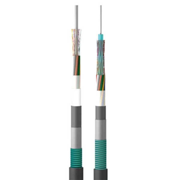
While nonarmored fiber optic cables don't require grounding due to their nonconductive properties, grounding is crucial when using armored fiber optic cables. Therefore, it is important to build a lightning protection system for fiber optic cables. How to Protect Fiber Optic Cable From Lightning? The major purpose of lightning protection systems is to conduct the high current lightning discharges safely into the Earth/ground. There are two main lightning. Fiber optic cable transmits data as light through glass or plastic strands, which means the fiber core itself carries no electrical current and requires no grounding. However, this does not mean every fiber optic installation is exempt from grounding requirements. Lightning-induced surges can travel through power lines, telecommunication lines, or nearby metallic structures and pose a. There are two main lightning protection grounding solutions in fiber networks, namely intermediate grounding and terminal grounding. These solutions use two ways of grounding for optical cable links both in domestic and foreign standards. However, because fiber optic cable has strengthened core, especially the direct-buried fiber optic cable has armoring layer.
[PDF]

This handbook covers the code of practice in protection circuitry including standard lead and device numbers, mode of connections at terminal strips, colour codes in multicore cables, dos and donts in execution. Also principles of various protective relays and schemes including special protection. Read this document and the documents listed in the additional resources section about installation, configuration, and operation of this equipment before you install, configure, operate, or maintain this product. Users are required to familiarize themselves with installation and wiring instructions. presentation of protection and control relaying. The report will identify methodology behind these practices, present issues raised by the integration of microprocessor relays and the internal logic and external communication configurations, ying. The objective of this presentation is to convey a basic understanding of protective relays to an audience of engineers already familiar with low voltage protective device coordination. HT panel protection relay. The HT power supply is received from GO switch and distributed to the. The handbook for protection engineers includes guidelines on protective circuitry, protective relay principles, and testing procedures for switchgear and relays. It covers standard codes, wiring practices, and norms for protecting generators, transformers, and lines, and provides detailed.
[PDF]

FS optical line protection switch features 1+1 backup and less than 15 ms fast switch to the standby fiber link that ensures business uninterrupted when malfunction occurs. An optical protection switch is a critical component in fiber optic communication systems designed to safeguard optical signals and infrastructure from damage due to power surges, signal overloads, or system failures. These switches ensure signal integrity, minimize downtime, and enhance network. 1+1 Optical Line Protection System for Fiber Protection, Bi-directional Protection in Dual Fiber, LC/UPC, Pluggable Module OLP (Optical Line Protection) is a device used in pairs, one at each end of the optical signal to protect network transmission line. OLP products include fiber optical line protection switches, optical bypass switches, optical cross connection, multi-channel. The FOSW-1x1 or 1x2 optical switch is based on opto-mechanical technology with proven reliability. OSW-W1x2 optical switch is a high performance electro-optical device, with low insertion loss (typic. In optical communication network, OLP monitors optical power of optical fiber and standby.
[PDF]

Numerical relay are embedded with specialized digital signal processor (DSP) as the computational hardware. By using DSP as the relay's processor, the relay is capable of meeting the fundamental protective requirements such as reliability, sensitivity, selectivity and speed . Thus, various protective devices are used to protect the power system, of which digital signal processor (DSP) numerical relays are capable of significantly improve protection operations. Therefore. Manuals and User Guides for Samwha DSP DSP-VIP-PM Motor Protection. We have 1 Samwha DSP DSP-VIP-PM Motor Protection manual available for free PDF download: Manual Samwha dsp DSP-VIP-PM Motor Protection Pdf User Manuals. View online or download Samwha dsp DSP-VIP-PM Motor Protection Manual. Many of the new protection relays are microprocessor based and are generally referred to as numerical relays. This means that signals from transducers are sampled at fixed time intervals, digitally encoded, and processed by equipment which resembles a computer to derive relaying information, e.
[PDF]

Precast concrete trench systems provide protection and easy access to power, communication, fiber optic, control, and signal wires and cables. Engineered precast trench is used in the power, utility, and transportation industries and can also be used in conjunction with catch basins, inlets, and. Completing Outside Cable Plant Installation. Underground cables are pulled in conduit that is buried underground, usually 1-1. 2 meters (3-4 feet) deep to reduce the likelihood of accidentally being dug up. In extreme cold climates, cables may need to be buried at greater depths where there. THE SOLID APPROACH TO TRENCHING. Made of a unique, patented. Trenwa is the original manufacturer of precast concrete trench and offers the broadest line of proven trench systems. Trusted by Industry Leaders: Trenwa has been a go-to partner for North American infrastructure projects for over for over 60 years. Request a quote today to see how our products can. Waskey's Precast Cable Trench System offers a durable, customizable solution for protecting and organizing critical infrastructure. If you need any help, be sure to reach out. Precast Concrete Trench for underground utility purposes. Primarily used for enclosure of electrical, communication, power cables, and piping.
[PDF]

Their core functions can be summarized as: enabling efficient cable branching, safe isolation, flexible control, and reliable protection of cable lines, thereby improving the reliability, flexibility, and maintainability of the power distribution network. A distribution box, often simply called a DB, is a crucial component in any electrical installation. Think of it as the heart of your building's electrical system. Just as a heart receives blood and pumps it to various parts of the body, the distribution box receives the main electrical supply and. Safety protection function in low voltage distribution boxes prevents electrical hazards and ensures reliable, secure power distribution for your operations. You rely on the safety protection function of a low voltage distribution box every day. These safety protection function features guard you. A distribution boxes is an essential device that safely and efficiently distributes electrical power to different areas within a building or facility. It is commonly used in homes, businesses, and industrial settings to control and protect electrical circuits. Today, electrical systems are essential for homes and industries. Understanding its significance.
[PDF]

The LC optical fiber pigtail is designed with a push-pull mechanism, enabling easy installation and removal without compromising on performance. Executive Summary: A fiber optic pigtail is one of the most commonly specified yet least understood components in structured cabling. Get the wrong connector type, the wrong polish, or skip proper fusion splicing technique—and you're looking at elevated signal loss, increased back reflection, and a. Fiber pigtails are simple in appearance, yet essential in function. They are the bridge between fiber optic cables in the field and the equipment or patch panels that manage them. By combining factory-installed connectors with spliced bare fiber, pigtails ensure that network installers can create. Fiber optic network design refers to the specialized processes leading to a successful installation and operation of a fiber optic network. It includes first determining the type of communication system (s) which will be carried over the network, the geographic layout (premises, campus, outside. All Rights Reserved. fCONSTRUCTION QUALITY REQUIREMENTS FOR FTTP & SSP Work Orders This document provides Construction Technicians, Construction Managers, FTTP/SSP Vendors, and Inspectors with the essential information to ensure a quality build and to successfully pass an Outside Plant Inspection. These terminations must be of the right style, installed in a.
[PDF]
The beam splitter is one of the important elements in optical waveguide circuits. To improve the performance of an optofluidic beam splitter, a microchannel including a two-stage main channel with divergent side walls and two pairs of inlet channels is proposed. Besides, the height of the inlets. M. Oulad Haddar; Improvement of optical characteristics of silicon based 1×3 beam splitter with photonic crystal waveguide. 20 January 2022; 2440 (1): 020001. 0075004 In this work, we propose a new structure of 1×3. In the second step of this work we propose an optimization of the conventional splitter design leading to suppression of the asymmetric splitting ratio to one-third of its initial value and to the improvement of the losses by nearly 2 dB. In addition, 50% size reduction of the designed structure. d for the power splitting ratios are vital for the adaptive optical networks and photonic computing. Conventional mechanisms such as thermo-optic, free-carrier, or mechanical tuning are usually volatile and require continuous p wer, limiting their suitability for low-frequency and low. Optical and Quantum Electronics This paper aims to study the design, simulation, and optimization of low-loss Y-branch passive optical splitters up to 64 output ports for telecommunication applications. For a waveguide channel profile, the standard material silica-on-silicon is used.
[PDF]
In this comprehensive guide, we'll walk through the best practices for installing various types of fiber optic cable, from patch cords to distribution fiber, and provide practical tips to ensure a successful installation. Correct patch-cord installation is essential for maintaining low insertion loss, stable return loss, and long-term reliability in both indoor and outdoor fiber networks. Proper handling, routing, cleaning, bend-radius management, and connector alignment ensure that the optical link meets design. Proper installation and regular maintenance of fiber optic patch cords play a crucial role in achieving optimized network performance, preventing signal errors, and extending service life. This guide addresses expert-certified best practices applied by professionals in the telecommunications, data. Proper connection of fiber optic cables is essential to harness these benefits fully, as even minor errors can lead to significant performance issues like signal loss. Whether you're connecting a data center, a corporate network, or a high-density fiber infrastructure, correct installation methods are essential. Yingda. In today's high-performance networks, fiber optic patch cables are the lifelines that ensure smooth data flow across switches, servers, and routers. Even the most advanced optical transceivers can only perform at their peak when paired with properly installed, clean, and precisely managed fiber.
[PDF]
* Bronze alloy bolts shall have a minimum tensile strength of 70,000 pounds per square inch. ** Bolts, cap screws, nuts, flat washers, locknuts: 18-8 alloy. Qualified to meet or exceed all the nationally recognized standards, including ANSI C119. 4 and NEMA CC1, the DMC Power system raises the quality, safety and productivity standard. Other aluminum compression connectors are made from com-mercially pure high conductivity wrought aluminum. Select type of connector from those listed below and follow the indicated procedure. ** Belleville Washers: 302 alloy. EX: TPC600-4N4-AA-GS TYPE TPC-N-AA Terminal Connector A C FIG. 3 T Terminal is designed to connect to aluminum or copper pads. Pad conforms to NEMA standards. 56 © 2011, AFL, all rights reserved. PP-3-00479. This publication contains the following new or updated information. This list includes substantive updates only and is not intended to reflect all changes. Added information about using a Top Hat Rail, catalog number 141A-AHR45, with a Adapter Extension Module, catalog number 141C-X40. Examples. We have recently reviewed our company's bus torque chart and found some of the values are in line with the bolt mfg suggestions (i. - 1/2" - 3/4" bolts). I started to update our torque chart to match the.
[PDF]

This article describes the anti-pumping relay, its definition, function, and circuit diagram. In a circuit breaker it is desired that when close and trip operation is performed on the circuit breaker with the closing coil energized, the subsequent closing operation should be prevented. So let's. Anti-Pumping relay is nothing but a NO contact, which means when the circuit breaker in closed condition the relay will be as NO point and if the circuit breaker in open condition the relay will be as NC Condition. The anti-pumping relays is connected in series with the circuit. An anti pumping relay (also called antipumping relay or Y-relay and ANSI 94 Trip or Trip-Free Relay) is a protective device that prevents a circuit breaker from closing repeatedly when a continuous close command is present. In simple terms, it stops your circuit breaker from “pumping” – which means. Anti-pumping relays are used in circuit breakers to prevent the breaker from closing unexpectedly after tripping. If the TNC switch fails (Trip normal close) or there is any problem with the CB (circuit breakers) closing circuit, the continuous CB (circuit breakers) close command can be extended to. Why is the Anti-Pumping Relay Used? A circuit breaker is a very important equipment for a high-voltage power system. It protects the system from high current or voltage during a faulty condition.
[PDF]

A new updated course will be released for sale during the spring of 2026. SFS 6002 Electrical safety -course is mandatory in Finland for all persons involved in electrical works: installers, managers, assistants etc. The course is valid for 5 years and shall be renewed to maintain the. Electrical qualification 1 (Electrical Safety Act 1435/2016 Section 66) The holder of electrical qualification 1 may work as an electrical work supervisor and supervisor of operations in all electrical and operational work. These regulations lay down binding requirements, which cover e. A person who builds, repairs or maintains electrical installations, or repairs and maintains electrical appliances must be professionally qualified, and Tukes must be notified before any such operations begin. The operators are called electrical or lift contractors. A company or a natural person. Electrical safety is not just a legal requirement – it's part of everyday workplace safety. Cad Sä Oy has developed the Electricity Passport, a new training model in which SFS 6002 training is carefully tailored to the specific electrical tasks each participant will perform in their project. The. Finnish electrical safety card (Sähkötyöturvallisuuskortti SFS 6002) is intended for people working in the maintenance and servicing of electrical installations, machines and equipment up to 1000 V in Finland.
[PDF]

Protect fiber optic cable connections:The joint box provides physical protection for the fiber optic cable connection parts to prevent damage to the fiber optic cable caused by external environmental factors such as moisture, dust, chemical corrosion and mechanical damage. Provide a stable. Fiber optic sleeves are protective devices used for fiber optic connections. Splice protection sleeve, usually made of plastic or metal, are used to secure and protect the fusion joint between two optical fibers. Fiber Cable Joint Box is attributed to the mechanical pressure sealing joint system. Fiber Cable Joint Box is a continuous protection device for supplying optical, sealing and mechanical strength continuity between adjacent optical. The optical fiber terminal box is the terminal joint of an optical cable, one end of which is an optical cable, and the other end is a pigtail, which is equivalent to a device that splits an optical cable into a single optical fiber. The user optical cable terminal box installed on the wall, its. Fiber Optic Splice Closure is designed to protect optical fibers from debris, dirt, dust, moisture and water. As much of the fiber system is outside in a harsh environment, these fiber optic splice closures are designed to meet the tough protection requirements of fiber-optic splices. UnitekFiber. Overview Application of Optical Fiber Splice Closure/Joint Box/Joint Closure: 1. CATV environment.
[PDF]

Arduino Safety Relay Box With Wall Socket : A relay is an electrically operated switch. In this project there is no real need to isolate one circuit. Relay rooms are essential in modern commercial or industrial buildings, serving as secure enclosures for electrical relays that manage power distribution and automation systems. Designing a relay room requires balancing technical precision with safety, efficiency, and future scalability. Many relays use an electromagnet to mechanically operate the switch and provide electrical isolation between two circuits. In this article, you will learn how to design an electrical control cabinet for optimal safety and efficiency, following some. This handbook covers the code of practice in protection circuitry including standard lead and device numbers, mode of connections at terminal strips, colour codes in multicore cables, dos and donts in execution. Reliable components ensure system faultlessness and durability. Modern design and user-friendliness. equipment of most. This is Part 1 in a series of tutorials that will show you how to build a Bussmann RTMR fuse/relay block. If you're not familiar with this product, it's a simple waterproof enclosure that allows you to connect accessories on your vehicle through relays and/or fuses. After reading this tutorial, you.
[PDF]
In electric power systems and industrial automation, ANSI Device Numbers can be used to identify equipment and devices in a system such as relays, circuit breakers, or instruments. The device numbers are enumerated in ANSI/IEEE Standard C37.2 Standard for Electrical Power System Device Function Numbers, Acronyms, and Contact Designations. Many of these devices protect electrical. List of device numbers and acronyms• 1 - Master Element• 2 - Time-delay Starting or Closing Relay• 3 - Checking or Interlocking Relay, complete Sequence• 4 - Master Protective. A suffix letter or number may be used with the device number; for example, suffix N is used if the device is connected to a Neutral wire (example: 59N in a relay is used for protection against Neutral Displacement); and suffixe.
[PDF]
