The primary application of fiber Bragg gratings is in optical communications systems. They are specifically used as. They are also used in optical and with an, or (OADM). Figure 5 shows 4 channels, depicted as 4 colours, impinging onto a FBG via an optical circulator. The FBG is set to reflect one of the channels, here channel 4. The signal is reflected back to the circulator where it is directed down and dropped ou.
[PDF]
The first in-fiber Bragg grating was demonstrated by in 1978. Initially, the gratings were fabricated using a visible laser propagating along the fiber core. In 1989, Gerald Meltz and colleagues demonstrated the much more flexible transverse holographic inscription technique where the laser illumination came from the side of the fiber. This technique uses the interference pattern of ultraviolet laser light to create the periodic structure of the fiber Bragg grating.
[PDF]
A compact fiber Bragg grating (FBG)-based strain sensor has been developed by embedding an FBG inside a 3D-printed structure, allowing the comparison of FBG responses across different filaments such a.
[PDF]
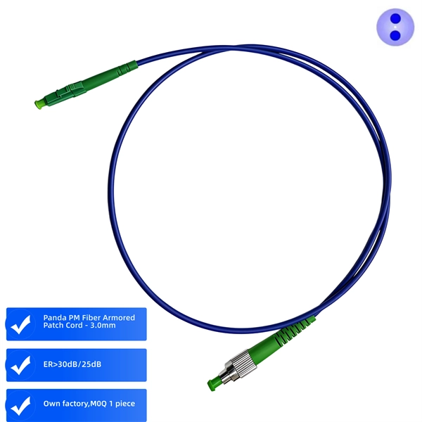
In this study, a new simulation method is proposed and verified for fiber Bragg grating patterned on polarization maintaining fiber(PM-FBG) using the transfer matrix approach. The method is designed to solv.
[PDF]
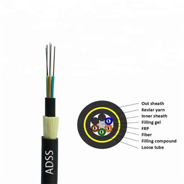
Fiber Bragg grating (FBG) sensors have emerged as advanced tools for monitoring a wide range of physical parameters in various fields, including structural health, aerospace, biochemical, and environmental applications. A fiber Bragg grating (FBG) is a type of distributed Bragg reflector constructed in a short segment of optical fiber that reflects particular wavelengths of light and transmits all others. This is achieved by creating a periodic variation in the refractive index of the fiber core, which generates a. A Fiber Bragg Grating (FBG) sensor is a specialized device that uses light within a glass fiber to detect environmental changes. This review provides a comprehensive overview of FBG sensor technology. Fiber Bragg grating (FBG) optical sensors have emerged as a leading technology for distributed strain and temperature measurement. Their unique attributes—compactness, immunity to electromagnetic interference, and multiplexing capabilities—make them a compelling choice for industries ranging from. Optical sensors based on Fiber Bragg Gratings (FBG) are becoming increasingly popular.
[PDF]
For high intracavity powers (e. tens of watts), however, detrimental thermal effects can occur, such as a shift of the reflection band and a decrease of reflectance. For not too high power levels, volume Bragg gratings can also be used in spectral beam combining. There are fiber Bragg gratings. An optical fiber grating is a small segment within an optical fiber altered to act as a selective filter for light. This treated area functions like a specialized mirror, reflecting a specific wavelength of light while allowing all other wavelengths to pass through. This microscopic structure. Optical fiber grating technology serves as a foundational stone in modern communication and sensing systems. This technology relies on periodic structures within optical fibers that modify the propagation of light, enabling a myriad of applications ranging from telecommunications to environmental. Fiber Bragg grating (FBG) sensors have emerged as advanced tools for monitoring a wide range of physical parameters in various fields, including structural health, aerospace, biochemical, and environmental applications. This review provides a comprehensive overview of FBG sensor technology. A fiber Bragg grating (FBG) is a type of distributed Bragg reflector constructed in a short segment of optical fiber that reflects particular wavelengths of light and transmits all others. This can be achieved by making use of fiber photosensitivity. At each interface between two regions.
[PDF]
In this guide, we'll walk you through the entire process of preparing fiber optic cable for splicing and termination to fiber connectors. We'll explore the necessary tools, safety precautions, and step-by-step procedures for cable connectors, mechanical and fusion. In this guide, you will find a chronological description of the fusion splicing process, the principal technical standards, and answers to the real-life questions network engineers and procurement teams may have. Therefore, we will also touch on cost factors, risk management, and best practices in. In this guide, we cover the basics of fiber optic splicing, how to perform splicing using two different methods, and finally some best practices to perform good fiber splicing. What is Fiber Optic Splicing and Why is it Needed? – #1. Two types of splices are used in fiber optic cabling one is Mechanical the other is Fusion. Before jumping into the physical steps, it's important to understand the two primary methods of fiber splicing: fusion splicing and. Learn how to splice fiber optic cable step by step in this complete guide! In this video, you'll see the full fiber splicing process — from fiber preparation, cleaving, and fusion splicing to final testing. For network managers and technicians, a poor splice can lead to significant signal degradation, network downtime, and costly troubleshooting.
[PDF]

Recommendation ITU-T L. 12 specifies splices of single-mode and multimode optical fibres. It describes suitable procedures for splicing that should be carefully followed in order to obtain reliable splices between single optical fibres or ribbons. Typical applications of these methods include aerial, buried, and underground splices. (2) American National Standard Institute/National Fire Protection Association (ANSI/NFPA) 70, 1993. § 1755. 370 - RUS specification for seven wire galvanized steel strand. 400 - RUS standard for. ation or liability to users of this publication. Existence of a standard shall not preclude any member or nonmember of NECA or FOA from specifying or using alternate construc Code (NEC) in effect at the time of publication. Because they are quality standards, NEIS® may in some instanc s go beyond. RUS standard for splicing copper and fiber optic cables. (FOA) was founded in 1995 to help develop the workforce to build the fiber optic networks to support a rapid expansion in communications and the Internet. The charter of the FOA was to promote professionalism in fiber optics through education, certification, and.
[PDF]
Recent advances in devices and applications of high-birefringence fiber loop mirror sensors are addressed. In optical sensing, these devices may be used as strain and temperature sensors, in a separate or in a simultaneous measurement. It is able to work over a long low refractive index analyte range from 1. This modified simple structured hexagonal PCF has high birefringence in the. Birefringent filters (or Lyot filters, as their implementation is most widely used in lasers) are popular radiation wavelength selectors. Their adaptations to fiber lasers are quite diverse and feature many original solutions.
[PDF]

This practical file details experiments conducted in Optical Fiber Communication, covering modulation techniques, system components, and performance analysis. An optical fiber is a glass or plastic fiber designed to guide light along its length, widely used in fiber-optic communication, which permits transmission over longer distances and at higher data rates than other forms of communications. Fiber-optic communication is a method of transmitting. Availability of plastic optical fiber (POF) The plastic optical fiber used in some of these experiments is available for science distributors. It is a 1000micron (1mm) POF available from several suppliers. FOA has samples available at no cost for teachers at schools in the US. Key experiments include amplitude modulation, frequency modulation, and pulse width modulation, aimed at understanding fiber optic systems. This document summarizes 10 experiments on optical fiber communication: 1. Studying a 650mm fiber optic analog link and the relationship between input and received signals. Optical fiber communication Laboratory Optical fiber communication Laboratory List of Experiments: 1. To set up a analog optical fiber link 2. To measure the characteristics of LED and LASER 5. Tech curriculum designed to provide a comprehensive understanding of optical fiber communication systems. This lab offers an immersive, web-based simulator that enables you to explore and experiment with key concepts in optical.
[PDF]

Optical Fiber Communication (OFC) revolutionizes modern telecommunications, enabling rapid data transfer across long distances with minimal signal loss. This comprehensive review explores OFC's historical evolution, core principles, components, and versatile applications. It traces OFC's. Additionally, optical fiber is lightweight and less susceptible to noise (no electromagnetic induction). Optical fiber consists of a cylindrical core that propagates light and a concentric cladding that surrounds it. The cladding's refractive index is slightly smaller than that of the core, which. Fibre optics and optical communications is the use of thin strands of glass for sending information encoded into light over long distances. Total internal reflection prevents light inserted into one end of the fibre from escaping through the sides. Keywords: Optical fibers, communication systems, data. Figure 1: Illustration of the inverse-square law of light intensity – the light's intensity diminishes with the square of the distance, which free-space optical signals must overcome (leading to very weak reception at long range) Figure 1 illustrates how light intensity decreases as distance.
[PDF]
Large-scale, densely distributed fiber Bragg grating (FBG) arrays have a wide range of applications in industrial safety surveillance. Due to the limitation of inscription pulse-width, most grating interrogator.
[PDF]

LC Connectors: Press the latch mechanism and gently pull the connector out. This guide outlines proper methods to safely remove fiber optic cable from modems in your home or office. As an experienced technology writer who has covered broadband advancements for over a decade, I aim to provide readers with trustworthy instructions endorsed by industry experts. Having. Unplugging a fiber optic cable from a modem is a task that requires careful handling to avoid damaging the delicate fibers within the cable. Fiber optic cables are different from traditional copper cables, as they use light to transmit data, and the connectors are more sensitive. This is a popular video tutorial that is often requested by viewers. Fiber optic cables are delicate and require specific handling procedures to maintain their performance and longevity. Is this something that requires a Verizon support tech or can I do it? If so is it as simple as disconnecting and reconnecting or would I have to call support to "reinitiate" my setup. Not my pic, but didn't feel like moving the. Unicom's Wireless Router is a multi-function device providing the following services: • Shared Broadband Internet Access for all LAN users. Page 5 All manuals and user guides at all-guides. com • Virtual Servers. This feature allows Internet users to access Internet servers on your LAN.
[PDF]
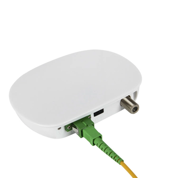
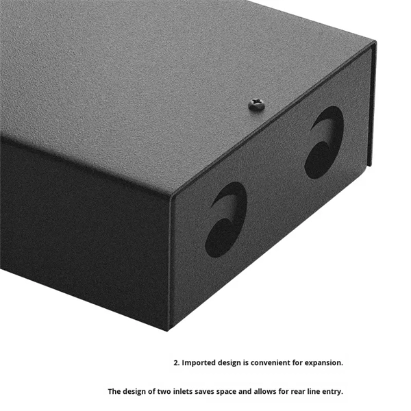
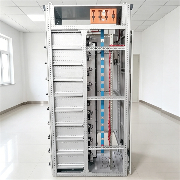
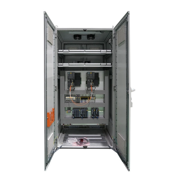
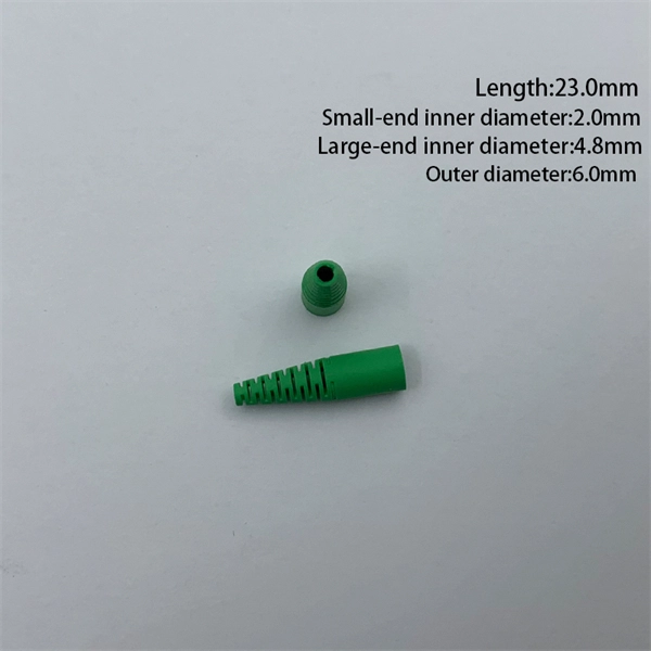
A distribution box serves as a central point for managing and distributing fiber optic cables. This device ensures reliable and efficient connectivity between various network components. By combining factory-installed connectors with spliced bare fiber, pigtails ensure that network installers can create fast, reliable, and cost-effective terminations. Without pigtails. A fiber pigtail is a type of fiber optic cable with a factory pre-terminated connector on one end and exposed fiber on the other. This design makes the fiber pigtail suitable for field termination using a mechanical or fusion splicer, playing a crucial role in the fiber optic cable installation. A Fiber Optic Termination Box is a small enclosure located at the terminal end of the fiber where it enters your customer premises. Its function is primarily to splice, secure, and protect the optical fibers connecting the incoming drop cable to the pigtail or patch cable. The connector end plugs into devices like transceivers or patch panels, while the bare end is typically fusion spliced to a fiber optic cable. You can splice the bare end with a fiber core of an optical cable, thus providing a connection for the fiber.
[PDF]

In short length cables a visual fault locator (VFL) can find where the cut is or find the bad connector at patch panels. For longer distance cables, the use of an OTDR is required. Once the fault is located, fusion splicers and splice-on connectors can be used to complete the repair. Fiber optic cables are the backbone of modern networks, delivering fast and reliable data transmission. Accidental cuts, breaks, or other damage can disrupt your network and cause costly downtime. With the right tools and techniques, you can efficiently repair damaged fiber cables and restore. Fiber optics offers advantages like EMI immunity and low attenuation (0. 2 dB/km), but it's fragile—susceptible to breaks, bends, and contamination. Repairs focus on restoring the light path with minimal signal loss (<0. A fusion. Visual inspection and specialized tools like OTDRs, OPMs, and VFLs are essential for identifying and locating physical damage or faults in fiber optic cables. Emergency restoration planning involves implementing backup power solutions, network redundancy planning, and strategies for prompt. Fiber optic cables are critical components of modern communication networks, transmitting vast amounts of data at lightning speeds.
[PDF]