Distributed Fiber Optic Sensing (DFOS) systems, using coherent light pulses, detect physical characteristics such as temperature and strain. DFOS enable localized measurements over long distances, leveraging Rayleigh, Brillouin, and Raman scattering. This review summarizes recent progress and emerging trends in multiparameter optical fiber sensing, emphasizing techniques that enable the simultaneous measurement of temperature, strain, acoustic waves, pressure, and other environmental quantities within a single sensing network. This technology is revolutionizing industries from infrastructure monitoring. Distributed Fiber Optic Sensing (DFOS) systems provide critical asset monitoring by utilizing standard fiber optic cables as sensors. These systems enable precise measurement of temperature, strain, and acoustic signals along the entire length of an optical fiber. Such capabilities.
[PDF]
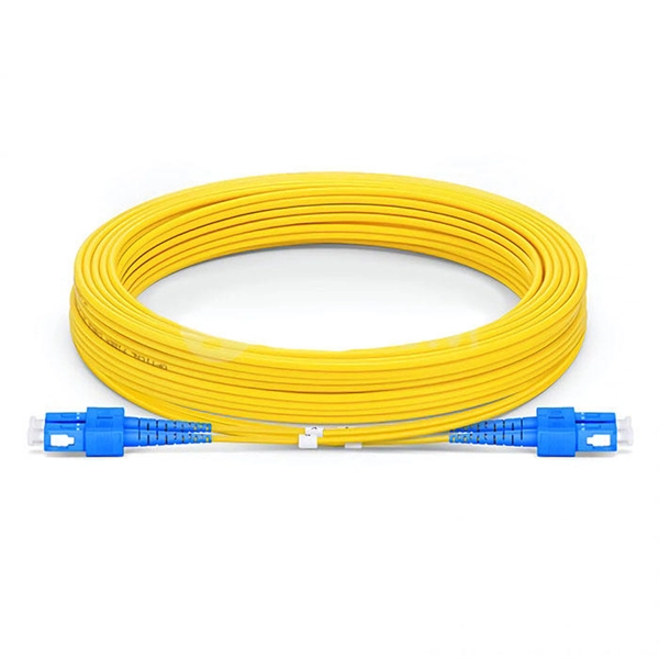
In network cabling, outdoor connections generally use fiber optic cables. When these optical fibers are installed or laid out, a Fiber Termination Box, or FTB, is used to distribute and protect the optical fiber link.
[PDF]

The formula for calculating electrical box size is: . The formula for calculating electrical box size is: . Free electrical load calculation tool for residential and commercial buildings. Calculate service entrance sizing, panel loads, demand factors, and ensure NEC Article 220 compliance. Important: Load calculations must comply with NEC Article 220 and local codes. Always verify calculations with a. How to choose a distribution box of the right size for a project based on load current? If you're like most electrical professionals, picking the right distribution box for your project can feel like navigating a maze. I've been in those shoes - staring at spec sheets, worrying about. The National Electrical Code (NEC) specifies minimum box sizes based on wire gauge and quantity. Proper sizing ensures safety, ease of maintenance, and compliance with regulations. This calculator helps you determine the minimum required box volume based on the number of wires, devices, ground wires, and clamps involved. This ensures compliance with electrical codes and prevents overcrowding. Choose a standard or custom box volume watch capacity update with clear pass or fail status plus tips examples CSV and PDF export for documentation Works for common sizes supports.
[PDF]
You can buy a manufactured 90 degree bend or make one on a cable tray bending machine but in this video I show you how to make one using a metal bar. Students trading aid on how best to put an internal 90 degrees bend in steel cable tray. more. The bends, tees, crosses, risers and reducers of wire mesh cable tray can be easily and quickly made live at the project by using a bolt cutter. Since the jaws of the bolt cutter drags a layer of zinc across the cut end and forms a protective layer. When a wire cable tray is cut, the fact that a. Before bending a cable tray, it is crucial to prepare it properly. This involves a few essential steps to ensure a successful bending process. First, marking is important📏. The space between your lines will be. Below are examples of fabricating the ET range to work around the needs of your electrical install project quickly and efficiently. Always use 2 splice plates per length of tray and SBH and CNH splice nuts and bolts to fasten them in place. EzyStrut splice bolts have a smooth head which should be.
[PDF]

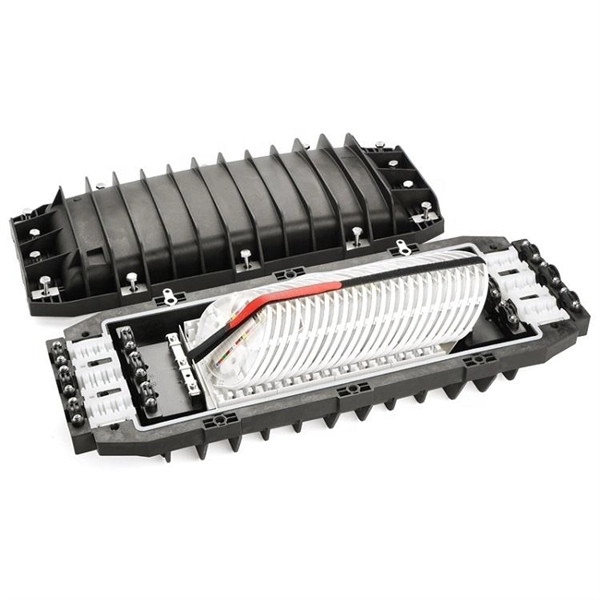
The goal is to fuse the two fibers together in such a way that light passing through the fibers is not scattered or reflected back by the splice, and so that the splice and the region surrounding it are almost as strong as the intact fiber. Fusion splicing is the process of fusing or welding two fibers together usually by an electric arc. Fusion splicing is the most widely used method of splicing as it provides for the lowest loss and least reflectance, as well as providing the strongest and most reliable joint between two fibers. Fiber Stripping: Selecting Precise Tools and Techniques Selecting the appropriate stripper will depend on the fiber coating diameter. This will typically be 250µm for bare fibers and 900µm for coated fibers. Reputable companies like Jonard, Fujikura, and INNO provide multi-hole strippers calibrated. Fiber misalignment and fiber geometry mismatch (e., core size, core-to-clad concentricity, core and cladding non-circularity, numerical aperture, etc. ) can result in real power loss across a splice joint. However, differences in the backscattering coefficients between two fibers can also show up. Fiber splicing means joining two optical fibers (permanently or temporarily) such that light guided in one fiber and reaching the joint (splice) can be transferred into the second fiber with low insertion loss.
[PDF]
This schematic details the products and procedures for the treat-ment of construction joints/cold joints in new concrete structures. Cold joints occur when a fresh concrete batch is poured against a partially hardened existing layer. As you know, concrete hardens through chemical reactions between cement aggregate, water, and air. This detail uses two elements in addition to ad-ditives and coaings to waterproof. Cold jointing concrete is a technique used to connect two separate concrete pours that have not fully bonded together, often due to delays or interruptions in the pouring process. This method involves preparing the existing concrete surface by cleaning and roughening it, applying a bonding agent to. Eng-Tips is the largest forum for Engineering Professionals on the Internet. Members share and learn making Eng-Tips Forums the best source of engineering information on the Internet! Congratulations GregLocock on being selected by the Eng-Tips community for having the most helpful posts in the. Managing cold joints is an important concept to grasp when working on concrete projects. For the completed structure to be strong and long-lasting, cold joints must be handled correctly. The term "cold" is used because the two concrete layers are not bonded properly, which can result in a weakened.
[PDF]

In the following tutorial, we will show how to wire 120V single-phase and 240V split-phase circuit breakers and loads inside a residential main panel. The figure below shows a typical breaker panel used for 120V and 240V circuits. Messy distribution boxes are dangerous and very hard to fix. You will learn to build a safe, efficient, and professional electrical system today. Circuit breaker wiring configurations involve organizing main switches, busbars. A breaker box, also known as a circuit breaker panel, is an essential component of any electrical system. It is responsible for distributing electricity throughout a building, ensuring that each circuit receives the proper amount of power. To understand how a breaker box works, it is helpful to. Each circuit is protected by a circuit breaker, a safety device that automatically shuts off power if it detects an overload or a fault. If you're looking to replace an old fuse box replacement or upgrade your home's power capacity, you'll be dealing with the load center or service panel. The distinction between 1P and 2P circuit breakers plays a pivotal role in determining the appropriate protection level for various circuits. When installing or troubleshooting a power distribution system, understanding how to correctly connect the main electrical supply to the control panel is crucial.
[PDF]

The following tutorial explains how to wire a 120V single-phase breaker and load points in a residential panel. 120V single-phase circuits are commonly used in homes for lighting and receptacle outlets. Plastic is lighter and good for indoor setups. Choose based on where you'll install the box. Inside the box, you'll find things like circuit breakers, busbars, terminal blocks, and wires. These parts control and distribute the electricity to different circuits safely. Some boxes also include DIN. The electrical service panel, often called a breaker box, acts as the central distribution point for all electricity entering a home. Whether you are an electrical contractor or a construction brigade, knowing how to properly and safely install distribution boxes is the basis of ensuring the safe operation of the entire system. This article details the process of installing them, which helps you comprehend distribution boxes. No description has been added to this video. Enjoy the videos and music you love, upload original content, and share it all with friends, family, and the world on YouTube. Jesse Kuhlman is a Master Electrician and the Owner of Kuhlman Electric based in Massachusetts. Jesse specializes in all aspects of home and residential wiring, troubleshooting, generator installation, and WiFi thermostats. Jesse is also the author of four eBooks on home wiring including.
[PDF]

The light-current-voltage (L-I-V) sweep test is a fundamental measurement that determines the operating characteristics of a laser diode (LD). Usually, a “laser diode module” is a combination of a laser diode and a photo detector (PD). The PD monitors. Author: the photonics expert Dr. Rüdiger Paschotta (RP) Definition: various test procedures applied to laser diodes in qualification, regular batch testing or burn-in Concept tree: Related: laser diodes optical power beam divergence optical spectrum Page views in 12 months: 1346 DOI: 10. 61835/8ab. Laser diodes are characterized by several crucial parameters that influence their performance and need to be verified during testing: Threshold Current: The minimum current required to initiate laser emission. Operating Current: The current at which the diode operates optimally. Output Power: The. L/I/V testing is universally regarded as the basic testing methodology for laser diodes, since many significant opto-electronic parameters can be measured or derived from the test results. Consequently, these are the most common tests performed during device development, production and. The versatile LIV Test System combines source and measurement devices into one system. The LIV Test System is a compact and cost-effective Source/Measure Unit (SMU) with the capability to output and measure both voltage and current of 64 to 1024 laser diode devices. The LIV Test System provides the.
[PDF]

A novel method for aligning multi-core fibers (MCF) provides a systematic approach for MCF splicing in the lab, in cable factories, and in the field. Splicing fiber optic cable is an extremely important phase for making dependable, high-speed communication infrastructures. Regardless of the type of fiber network you're deploying, be it for telecom, enterprise data centers, or smart city infrastructure, fusion splicing provides the benefits of. This is where fiber optic cable splicing—the process of creating a permanent, high-performance join between two fiber ends—becomes critical. For network managers and technicians, a poor splice can lead to significant signal degradation, network downtime, and costly troubleshooting. At Turn-Key. W. Zheng, "Automated Alignment and Splicing for Multicore Fibers," in Optical Fiber Communication Conference/National Fiber Optic Engineers Conference 2013, OSA Technical Digest (online) (Optica Publishing Group, 2013), paper OM3I. However, realising its potential depends on one critical process, which is achieving ultra-low-loss fusion splices that maintain performance and. This guide reveals the secrets to fusion splicing with little fluff—just proven, straightforward techniques refined from years of work in the field. The guide provides the complete workflow, covering safety precautions, tool selection, fiber preparation, fusion operation, quality control, and.
[PDF]

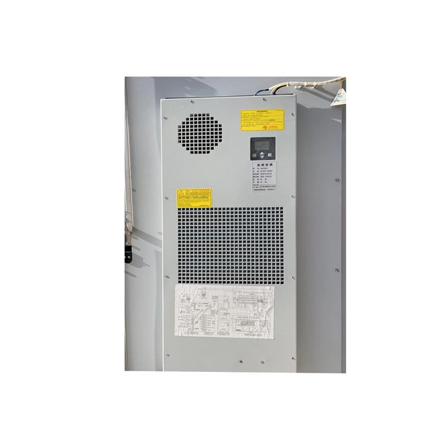
This publication shows how to wire and install the 4010-9825 24V Distribution Block into a 4010 Fire Alarm Control Panel (FACP). Refer to the 842-058 Field Wiring Diagram for additional wiring information. 1 Transformer connection: Two red wires connect to AC 220V input port, while two yellow wires connect to AC input port of main board (had connected by the factory. 2 DC12V battery connection: Red wire on the circuit main board connects to the positive pole of acid-lead battery while black. Notify the carrier and call Telect's Customer Service Department at 1-800-551-4567. Keep the container until you have checked equipment operation. Use the original, undamaged container if you are instructed to return. Learn how to wire a distribution box step by step! This video shows real on-site footage of electrical installation, demonstrating safe and standardized wiring methods used by professionals. Such a system, however, does not assure. Material preparation: Prepare the required circuit breakers, wires, wiring ties and other materials, and ensure that they meet the design drawings and installation requirements. Location determination: Determine the installation position of the circuit breaker according to the position of the.
[PDF]
An optical time-domain reflectometer (OTDR) is an optoelectronic instrument used to characterize an optical fiber. It is the optical equivalent of an electronic time domain reflectometer which measures the impedance of the cable or transmission line under test. An OTDR injects a series of optical pulses into the fiber under test and extracts, from the same end of the fiber, light that is scatter. Reliability and quality of OTDR equipmentThe reliability and quality of an OTDR is based on its accuracy, measurement range, ability to resolve and. The common types of OTDR-like test equipment are: 1. Full-feature OTDR: 2. Hand-held OTDR and Fiber break locator: 3. RTU in RFTSs:. In the late 1990s, OTDR industry representatives and the OTDR user community developed a unique data format to store and analyze OTDR fiber data. This data was based on the specifications in GR-196, G.
[PDF]
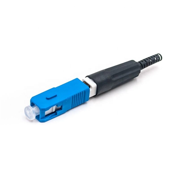
We release the data list we used for Kinetics-400 (k400, train list link, val list link) and Something-something-v2 (ssv2, train list link, val list link), which reflect the class mapping of the released models and the videos available at our side. Amphenol ST adapters are manufactured to be mechanically and optically intermateable with ST and STII products. Ideally suited for Datacom and Telecom applications in densely packed patch panels. Discover Amphenol FOP's ST and STII fiber optic adapters-engineered for high-density telecom/datacom. FiberSource ST to ST Adapter with Phosphor Bronze, Alignment Sleeve, Black Metal Body, DD-Hole Mount. ST adapters come with a ceramic sleeve for both singlemode and multimode adapters. The simplex housing is available in double D footprint type. ST adapters have high precision alignment sleeves for. The SENKO ST Adapter is a versatile and reliable component modern fiber optic networks. SENKO's ST simplex and duplex adapters are available with a robust metal housing, ensuring durability and longevity in various environments. It is strongly recommended that the Kinetics-400.
[PDF]
You can search for HS Codes for different categories of goods, their duty rate and the related Regulatory Authority if a permit is required. Total Import/Export Value in thousands of US Dollars current value. Monthly Total of Imports and Exports Value in thousands of US. The agreement eliminated tariffs for GCC member states on 426 items (primarily food and medical products) and applies five percent import duties on most commodities imported from countries outside the GCC, except alcohol and tobacco which are assessed duties at 125 and 100 percent, respectively. Export Bahrain has signed a Memorandum of Understanding (MoU) with the Portuguese Industrial Association (AIP), in a move aimed at expanding economic ties and strengthening trade and investment. Where HS Codes are not stated on Commercial Invoice, Customs Authorities may apply penalties The following are trade agreements with Bahrain that can benefit from customs reduction rate. To benefit from customs reduction, Certificate of Origin accompanied with Commercial Invoice are required Top. Receive an instant quote, look up rates, and book a shipment – all in one place. Trusted by more than 100,000 customers worldwide. Retail, auto, electronic parts, and more. Ship perishables with end-to-end visibility. Services to ship Out-of-gauge cargo. Get fixed prices and.
[PDF]

A ladder type cable tray tee is a fitting used to create a branch in a cable tray system, allowing cables to be routed in three directions. Its "T" shape provides a secure and efficient way to split cables from a main tray into two separate paths, ensuring organized and flexible. A cable tray tee and tee cover are components used in cable management systems to support and protect electrical and data cables. Here's a brief explanation of each:. Rigid steel cable tray tee fitting with zero tangent, safety bottom, and full accessory support. ventilation to heat producing cable such as power communication and other with the same or different width of the cable run. All fittings are available in sizes and types corresponding to the straight cable tray sections. These fitting are including: elbow, horizontal cross, vertical inside. NOTE : Equal or un equal tees can be supplied. When ordering state widths W1xW2xW3.. Office: 147/22 Nguyen Sy Sach Street, 15 Ward, Tân Binh Dist, HCMC,VN. Is it possible to connect 2 cabletrays with a "branch piece (left picture)" instead of a "tee (right picture)". The tee has 3 connectors, the branch piece only has 1 connector. I would like to ajust the "Type properties -> Fittings -> Tee" with the branch family, but can't get it accomplished.
[PDF]