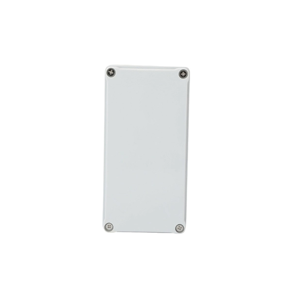
Attach a ground wire from one of the threaded studs (A) at the bottom of the housing, to the mounting plate (B). The ground resistance between all system parts shall be <. The protective grounding system, which includes conductor grounds and worker bonding, must be engineered to protect workers from hazardous voltages that can be created by line reenergizing, lightning, or induced oltage. If more than one crew is working independently on the same deenergized line or. Power from factory ground must be installed by a qualified electrician. Each DISTRIBUTION BOX and controller must be grounded. On the US market, a 5. 26 mm 2 (10 AWG) ground wire must be used, and in all other markets a 6 mm 2 must be used. The neutral conductor is typically the grounded conductor connected to the system's neutral point, carrying current under normal operation. Grounding electrode conductors must be connected at. The correct connection method of Distribution box grounding wire mainly includes the following steps: 1. Whether you're a seasoned pro or just starting out, this comprehensive guide will give you practical. This technical article covers protective grounding requirements for steel tower and wood pole supported transmission and distribution lines, and insulated power cables. Protective grounds must be installed so all phases of lines or cable are visibly and effectively bonded together in a multi-phase.
[PDF]
This paper analyzes the basic principle and function of relay protection, summarizes the common fault types, and analyzes the fault analysis methods and treatment measures combined with actual cases. A method of fault tracking for relay protection devices is presented in this paper. Fault tracking means that after the failure of relay protection devices, the anomalies and warning informa-tion are obtained through data-mining technology, and then, the fault tracking algorithm is used. Relay fault diagnosis refers to the process of identifying and analyzing faults or abnormalities in protective relays. However, in actual operation, the relay protection device may cause failure due to hardware failure, software problems or external. For a long time, the fault diagnosis technology of relay protection consists of isolated cases and does not have a systematic method.
[PDF]
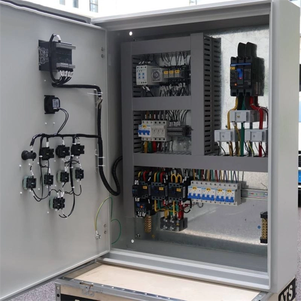
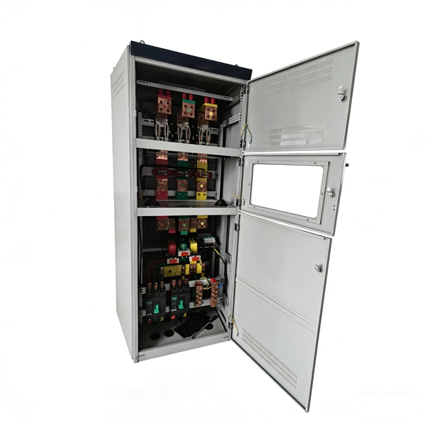
The vertical distance between the bottom surface of fixed distribution box and switch box and the ground shall be greater than 1. 3m and less. Flameproof enclosure (Ex d IIB+H2), which can be used as feed distribution equipment in control and distribution system (such as distribution box, switch box of main circuit, control box, terminal box or motor starting box etc. ) ·Enclosure: stainless steel. Equipped with specialized hinge. The Unified Facilities Criteria (UFC) system is prescribed by MIL-STD 3007 and provides planning, design, construction, sustainment, restoration, and modernization criteria, and applies to the Military Departments, the Defense Agencies, and the DoD Field Activities in accordance with USD(AT&L). Structural requirements for explosion-proof distribution boxes: 1. The. Explosion-proof distribution boxes aren't just metal containers; they're engineered life-savers designed to contain potential disasters before they start. When lives and million-dollar facilities hang in the balance, you don't want generic solutions. These specialized enclosures are built tougher. The Code of Federal Regulations (CFR) is the official legal print publication containing the codification of the general and permanent rules published in the Federal Register by the departments and agencies of the Federal Government. The Electronic Code of Federal Regulations (eCFR) is a.
[PDF]
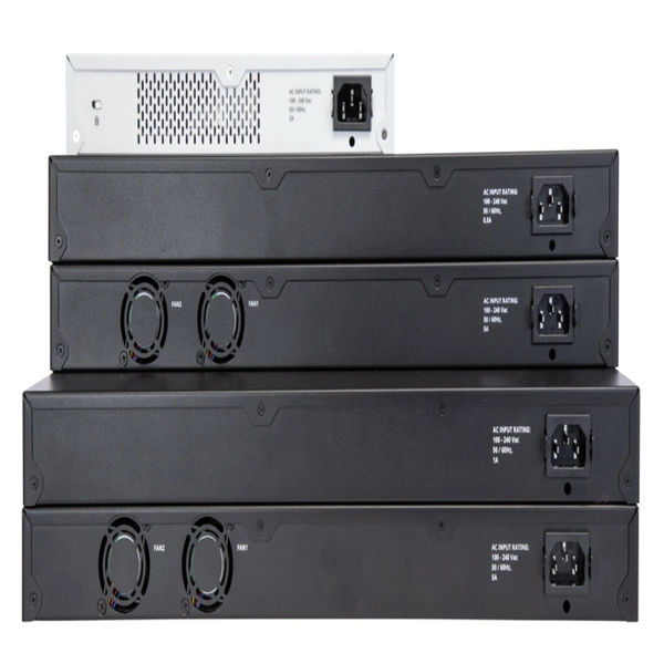
This article discusses such episodes, known as data center outages, looks at their causes, and shares best practices for preventing them. Malfunctioning Hardware 3. Environmental and Natural Disasters 6. Software Failure. 2025 revealed how data center outages, from fires and mechanical failures to hyperscale cloud region events, can cascade quickly in an AI-driven world, highlighting the growing importance of physical resilience, control-plane reliability, and clean recovery. Physical infrastructure failures, such. As hyperscale AI campuses expand and real-world attacks strike supporting systems, the gap between how data centers operate and how they're protected is becoming harder to ignore. AWS Outage: What Are the Lessons for Enterprises?. Fault-tolerant systems are systems that are engineered to detect failures, isolate faulty components, and recover quickly without significant impact on operations. This is achieved through a combination of physical, logical, and data redundancy, sophisticated fault detection mechanisms, and. Data center failures can be caused by a variety of factors, some of which are common and impact most people (such as human error), while others are rare. Whether it is rare or not, the impact is usually the same: lost productivity, poor service that affects customers or staff, and costs more. Introduction to Fault Detection through BMS 2. Fault Detection & Diagnostics (FDD): Component Breakdown 5. Predictive &.
[PDF]

Cable Trays* — Max two 24 in. (610 mm) wide by max 6 in. (151 mm) deep open-ladder cable tray with channel-shaped side rails formed of 0. 54 mm) thick aluminum or min 0. In practice, cable tray dimensions are a system of interrelated measurements —width, depth, length, and material thickness—that directly affect cable fill compliance, heat dissipation, structural loading, and long-term expandability. From an engineering standpoint, cable tray dimensions are not. Perforated Cable Tray System expertly constructed from high-grade stainless steel, offering exceptional durability and resistance to corrosion. With side height 100mm. A properly designed and installed cable tray system will provide. Studs — Wall framing to consist of wood studs or channel shaped steel studs. Wood studs to consist of nom 2 by 4 in. Additional studs shall be used to completely frame. Best Size: Here, deep trays (75mm to 150mm) are used since power cables are typically thick and heavy. Data cables, such as your Wi-Fi or computer ones, are extremely sensitive. They do not get hot; however, they do not like to hang or sag. In case a data cable folds in an excessive manner, the. ect the minimum bend ra-dius for cables as they exit the bottom of the cable tray. A rung spacing of 6 to 9 inches (150 to 230 mm) is preferable when the cable tray cont d for instrumentation and control applications that require additional protec eferred to support and protect numerous small.
[PDF]
Busbars are essential components in electrical power systems, designed to distribute power efficiently within switchgear, panel boards, and distribution boards. Made from copper or aluminum, they serve as a central point where multiple circuits can connect, ensuring stable and. A bus bar (also spelled busbar) is a metallic strip or bar used in electrical power distribution to conduct electricity within a switchboard, distribution board, substation, or other electrical apparatus. Its primary role is to carry large current loads and connect multiple circuits together. In virtually every piece of electrical equipment—from switchgear and power distribution panels to EV battery packs and AI data centers—busbars play a vital, if often unseen, role. These components are the silent conductors of power, ensuring efficient energy distribution, reliability, and compact. Busbars (bus bars) are a type of electrical conductor that, compared to traditional cables, allow for the transmission of current in a safer and more flexible manner. They ensure efficient and effective energy distribution, successfully powering single- and three-phase devices and machines, and. Busbars offer a clean, efficient way to manage power distribution, simplifying complex wiring jobs and boosting reliability.
[PDF]
Attach a ground wire from one of the threaded studs (A) at the bottom of the housing, to the mounting plate (B). The ground resistance between all system parts shall be < 0. Power from factory ground must be installed by a qualified electrician. Each DISTRIBUTION BOX and controller must be grounded. On the US market, a 5. This position is the connection point of the grounding wire in the. Today, we're diving deep into the world of distribution box grounding, breaking down the standards, and shining a light on those sneaky mistakes that even experienced electricians sometimes make. Whether you're a seasoned pro or just starting out, this comprehensive guide will give you practical. How to make proper & safe electrical ground wiring connections in the box: This article describes options for connecting a metal electrical box to the grounding conductor & connecting the grounding conductor to a fixture such as a ceiling light or ceiling fan. It ensures stability and provides a critical path for fault current, preventing severe shocks and fire hazards. This guide covers the essential principles and procedures for grounding an electrical panel per the National. To safely ground a metal box, connect an equipment grounding conductor (typically a bare or green insulated wire) from the box to the main electrical panel's ground bus bar. Use a green grounding screw to secure the wire to a designated threaded hole in the metal box itself. This critical step.
[PDF]
These are single- or multi-conductor control cables designed for use in trays or substations. They feature insulation made from XLPE, EPR, PE, or PE/PVC, and are protected by jackets made of CPE, PVC, or LSZH. Our cables are suitable for various installations, including cable trays, direct burial. Substation Control Cable is a general purpose control cable, which is primarily used in industrial and utility applications, for distribution or control circuits and for the interconnection of operation of protective devises. Substation Control Cable can be installed in open air, in ducts or. Lightera products are used in electrical substation automation applications. Competitively priced and designed for minimal environmental impact, this cabling solution allows for reliable. Abstract:The design, installation, and protection of wire and cable systems in substations are covered in this guide, with the objective of minimizing cable failures and their consequences. These cables are crush resistant, have a high degree of varying temperature ranges (from -50c to +75C), are easy to terminate, and can withstand any environment. Power Cables High Voltage (HV) Cables: Used to transmit.
[PDF]
Pilot-wire relaying is an adaptation of the principle of differential relaying to line protection and functions to provide high-speed clearing of the line for faults anywhere on the line. Pilots include wire pilot (us.
[PDF]

A wiring diagram for a photocell and timeclock controller provides a step-by-step guide for installing and connecting all the components in a light system. It shows exactly how each component fits into the overall scheme of things, as well as what wires to use and which connections to. Intelligent Lighting Controls' wiring diagrams show detailed schematics of our solutions. A lighting control module is the “control center” for your lighting system. It acts as a bridge between your physical lighting fixtures and the smart systems that manage them. Instead of relying solely on traditional wall switches, you can control your lights via remotes, mobile or web apps. This guide will discuss the steps needed to integrate with URC Total Control. Commission CSI Controllers Step 2. Locate/Download latest TCM files/Module Step 3. Network Setup Step 6. Supports DALI V2 compatible switches and sensors, works out of the box. Simple and easy setup. ControlByWeb® IoT controllers are a great fit for lighting control in edge applications. Understanding the components that make up a modern lighting system, and how they relate to one another is key to ensuring the best performance and.
[PDF]

