
FiberMall MPO16 APC Y Splitter Cables 10m are designed for 800G QSFP-DD/OSFP DR8/OSFP XDR8 optics direct connection and support 800G transmission for Hyperscale Data Centers. Multimode PLC Splitter is a passive optical device used to split incoming signals into two or more output signals. They're capable of operating over a broad wavelength range from 650 nm to 1350 nm (Typ. 650nm, 850nm and 1300/1310nm). 5/125 (OM1, OM2, OM3 and. High-Quality Construction: This Fiber Optic PLC Splitter is manufactured by UT-KING, a reputable brand known for its reliable products, ensuring a durable and long-lasting performance. Optimized for FTTH Solutions: Designed for use in Fiber-to-the-Home (FTTH) applications, this 1x2 OM3 PLC Splitter. Optical coupler is an optical device that combines or splits power from optical fibers. Note: All insertion loss and insertion loss referenced without connectors. Takfly, established in 2000, has been manufacturing. Optional split ration 1:99, 2:98, 5:95, 10:90, 20:80. USource OM3 Fiber Coupler is a 1x2 or 1x3 passvie optical multimode splitter based on FBT (Fused Biconic Taper) technology, packaged in mini ABS box module or steel tube, split into different rations 1:99, 2:98, 50:50, 10:90, 20:80.
[PDF]
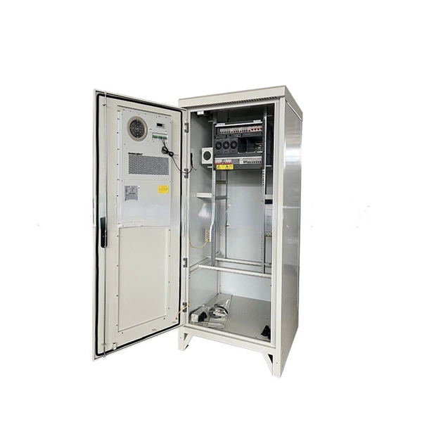
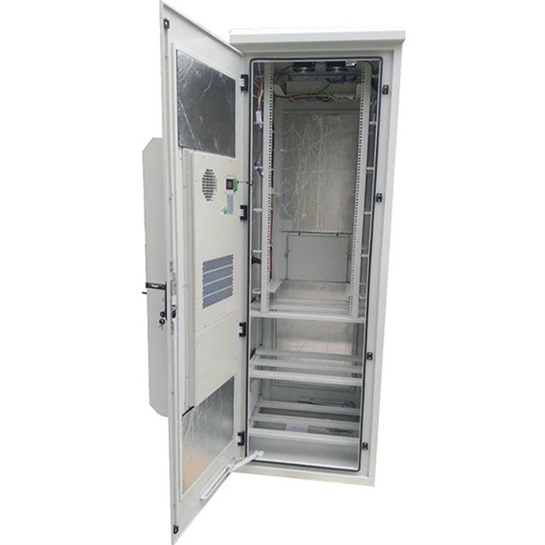
These products are highly integrated, compact in size, structurally compact, safe and reliable in operation, easy to maintain, and portable. In distribution systems, they can be used in ring network distribution systems as well as in dual power supply or radial terminal distribution. High voltage and low voltage complete sets occupy a significant place in modern electrical engineering as they are responsible for safe, secure, and efficient power distribution to all types of industries. They are known as complete switchgear assemblies because they integrate inside them such. Electricity plays a critical role in ensuring national well-being and livelihoods, and the stable development of the power industry drives socio-economic progress. To achieve structural adjustment and transformation in the power industry, the foremost priority is enhancing the performance of. Our high and low voltage complete electrical equipment solutions are designed based on a deep understanding of the current development trends in the power industry and accurate predictions of future power demand. It is mainly used to protect, control and isolate electrical equipment. Its primary functions are to cut off the power supply of equipment to facilitate subsequent maintenance. Senior Electrical Engineer, with 12 years of experience in high and low voltage switchgear installation, commissioning, and overseas project technical support. Currently, Thor is the Technical Department Manager at Weisho Electric Co.
[PDF]
This contribution discusses the parameters affecting the thermal state of the lead-acid battery. Lead-acid batteries are among the most widely used energy storage solutions across various industries, including automotive, renewable energy, and backup power systems. However, like most battery technologies, their performance can degrade significantly under certain environmental conditions. It was found by calculations and measurements that there is a cooling component in the lead-acid battery system which is caused by the endothermic discharge reactions and electrolysis of water during. One of the most critical processes in the production of lead-acid batteries is the electrochemical formation of the plates. In the case of VRLA (valve-regulated lead-acid) batteries with glass mat separators, this process is carried out post-assembly, after the plates are sealed in the battery. Battery performance is highly sensitive to temperature extremes. Cold weather, thermal cycling, and fluctuating charge/discharge conditions can significantly impact efficiency, reduce amp-hour capacity, shorten lifespan, and hinder rechargeability. However, a fully charged lead-acid battery can function down to -50 degrees Celsius. We offer products for managing issues like thermal conductivity, thermal cycling, thermal shock, and extreme temperatures.
[PDF]
Finally, we elucidate the latest developments and vital features of modern 850 nm VCSELs for high-speed interconnects. Introduction. Nedinsco delivers highly advanced optronic systems for reconnaissance and surveillance, trusted by military forces worldwide. Equipped with next-generation sensors, our systems significantly enhance visibility. We offer solutions for armored vehicles, unmanned ground vehicles (UGVs), drones (UAV's). Our company's advanced optoelectronic systems represent a technological leap forward in border security capabilities. Introduction Since the invention of the VCSEL by Iga's group in 1978 [1, 2] and the demonstration of its first room-temperature (RT, 300 K) operation in 1988 , many groups. Northern Macedonia has purchased three mobile surveillance and surveillance systems from the MUSON – MUSON 20FM series, developed by the Bulgarian company Opticoelectron, reports the BulgarianMilitary. Customized payload features, as well as FOG based stabilization provides ultra-long-range observation and tracking capabilities. The basic instruments like: VIS day camera, low light, SWIR camera, LWIR or. High-speed optoelectronics is central to many important developments in the communication, computing, sensing, imaging, and autonomous vehicle industries. With a sharp rise of attention on energy efficiency, researchers have proposed and demonstrated innovative materials, high-speed devices, and.
[PDF]

Select the correct wavelength and set your reference. You measure optical power in dBm or insertion loss in dB. Consistent procedures ensure accuracy. Measure total signal loss from fiber, connectors, or splices. Optical fiber attenuation is the attenuation per unit length of optical fiber, and the unit is dB/km. When connecting two optical fibers, there will be loss inside any connector or joint. Consistent measurement techniques. While optical power meters are the primary power measurement instrument, optical loss test sets (OLTSs) and optical time domain reflectometers (OTDRs) also measure power in testing loss. TIA standard test FOTP-95 covers the measurement of optical power. Optical power is based on the heating power. Light Source: The CMA5 Series Light Sources provide an economical and stable laser source for use in point-to-point attenuation measurement. They feature a rugged design, built to withstand the difficult testing environment of fiber optic cable installation and maintenance. The CMA5 Light Sources. When talking about optical measurements, wavelength basically means how far a wave pattern repeats itself, usually measured in nanometers (nm). Commonly, a power meter on its own is used to measure absolute.
[PDF]

Optical return loss is the amount of light that is reflected back to the source, this reflected light is measured at each connector and splice at each point over the entire fiber link. This is always measured in dB (decibels) and will be displayed as a negative number. The closer the number is to. The polish of a singlemode fiber endface plays a significant role in reflectance. Understand what you need before you specify. The Institute of Electrical and Building the ORL story Electronics Engineers (IEEE) recently Within a fiber-optic channel or path-released new specifications within way. Optical Return Loss (ORL) in fiber optics refers to the amount of light that is reflected back toward the source in a fiber link. ORL is usually expressed in decibels (dB) as a positive value, with. Return loss (RL) is also called reflection loss. When high-speed signals enter or exit a part of an optical fiber, such as an optical fiber connector, discontinuity and impedance mismatch may cause reflection, which is the return loss of an optical fiber. Poor ORL is commonly caused by dirty connectors, poor splices, mismatched connector types, or damaged fibers. ORL is measured using ORL meters. Home Coherent Optics Optical Return Loss (ORL) Explained Comprehensive Guide to Understanding and Managing Back-Reflections in Fiber Optic Systems What is Optical Return Loss (ORL)? Optical Return Loss (ORL) is a critical parameter in fiber optic systems that quantifies the amount of light.
[PDF]
We deliver custom-made cable trays to meet the needs of your project, ensuring easy installation and reliable support for your cables. The nVent CADDY Wire Basket Tray System is an industry leading continuous pathway support solution for today's high-performance cabling systems. This robust. See our products in a new more user-friendly way We have wire trays, data racks and all accessories you need to install your cables in an easy, fast and high qualitative way. Nordic Wire Tray becomes Nordic Wire Tray. New name, new look, same Nordic quality We continue to drive innovation in cable. How can we improve? Choose from our selection of wire trays, including over 850 products in a wide range of styles and sizes. Same and Next Day Delivery. ShowMeCables stocks a range of cable management, low voltage wire holders including Duct, Spools, D-Rings, Grommets, Lacing Bars and Strips, Neat-Patch, Wall-Mounted, Vertical, Horizontal, Cable Tray and Cable Tray Accessories. Brands include ShowMeCables, L-com, ICC, Middle Atlantic, Panduit, Hosa. Count on Monosystems to deliver products, solutions and expertise that are tailor-made for the market you serve. For over 50 years, we have dedicated ourselves to providing Industry with best in class wire management solutions and to helping solve mission critical issues. Discover the benefits of each system to make an informed decision tailored to your specific application. We also offer a wide range of accessories in all.
[PDF]

In this guide, we take a deep dive into the design, performance, and applications of liquid cold plates, which are essential for thermal management in industries like data centers, telecommunications, aerospace, and defense. In this study, we conducted an experimental study on the heat sink performance at a constant volumetric airflow rate under various pressure conditions and verified the effect of the change in the density of the working gas on electronics cooling performance. First, we measured the flow rate of. Electronic circuits and systems designed for earth orbiting space applications and outer planetary exploration are required to operate reliably and efficiently under extreme temperature conditions. This requirement is dictated by the fact that the operational environments associated with some of. Cold plate cooling systems are revolutionizing how high-performance electronics manage heat in demanding environments. EMS providers deliver production-ready electronic systems for applications such as avionics, radar, communications, and unmanned platforms, with processes. For aerospace and space applications, where packaging and the optimal use of space, weight, and power are important, adequate and efficient cooling is a limiting factor due to the increased heat flux rates from compact-design electronic units. From a thermal energy management perspec-tive, immersion cooling is better than.
[PDF]

GOOD WILL INSTRUMENT (SUZHOU) CO. Browse online or download User Manual for Equipment Gw-instek GOS-652G. GW Instek GOS-652G User Manual 50MHz Cursor Readout With Delayed Sweep.. GOS-658G 20MHz Cursor Readout... GOS-652G 35MHz. Caution statements identify conditions or practices that could result in damage to this product or other property. THIS APPLIANCE MUST BE the letter E or by the earth symbol or coloured Green or Green & Yellow. EARTHED The wire which is coloured Blue must be connected to the terminal which is. y have a fraction of the total loss compared to fiber-based equivalents. FBG also provides a latency in the o der of nanoseconds as compared to microseconds in fiber-based solutions. The FBG based DCMs are designed to perfectly mimi the dispersion and dispersion slope characteristic of G. 652 fiber. g sensitivity and low water-peak level. Together they allow unlimited use of the whole telecom wavelength win ow for a great variety of applications.. GOS-653G Basic... GOS-622G. The GOS-653G/652G Series is an example of classic analog oscilloscope design. The GOS-653G /652G cover a broad range of industry applications, such as product design, assembly lines, repair & servicing, and educational purposes for EE laboratories and class experiments. Coupled with various trigger.
[PDF]

The max insertion loss of a fiber patch cable is 0. 75 dB (the maximum acceptable value) in the TIA standard. Insertion loss (IL) and return loss (RL) are key performance indicators of fiber optic patch cords. This article explains their concepts, standards, testing methods, and FiberMania's quality assurance workflow to ensure optimal network performance. Fiber optic patch cords are crucial components in. A: Fiber optic loss refers to the reduction in signal strength as it travels through the fiber optic cable. This can be due to various factors, including attenuation, connectors, and splices. Q: How is fiber optic loss measured? A: Fiber optic loss is typically measured using an Optical Loss Test. The estimate, called a "loss budget" is calculated using typical component losses for each part of the cable plant - the fiber, splices and/or connectors. If the measured loss exceed the calculated loss by a significant amount (remembering the inherent uncertainty in all measurements), the system. Insertion loss is usually shortened to IL, and the unit of measurement for insertion loss is dBm. ) in transmission systems. It is the power attenuation of the signal after. At TARLUZ, we specialize in manufacturing high-performance fiber optic patch cords that comply with global industry standards, ensuring optimal signal integrity and long-term stability.
[PDF]
This test station do the auto-testing on 12 core (24 core) for insertion loss and return loss, highly efficient multi-core fiber insertion and return loss measurement and make high precision on the measurement result with OTDR mandrel free technical adopting. (MPO/MTP) mandrel free insertion loss test station is specially design for multi fiber testing. It combines three. •Compact benchtop instrument for all-in-one operation optic components quickly and accurately. The system has a or LED source for multi-mode applications. With a dual two wavelengths in less than 1 second. ILM-100 system comes integration into test systems. the measurement result with OTDR mandrel free technical adopting. Automatically complete the 12-core (24-core) dual-wavelength IL&RL test. The application of OTDR winding-free technology has greatly improved the insertion. You can make an inquiry about this product. Your e-mail will not be leaked.
[PDF]

Fiber optic loss calculation formula: Total link loss (LL) = Cable attenuation + Connector attenuation + Fusion attenuation [Note: If there are other components (such as attenuators), their attenuation values can be added]. Intrinsic Optical Fiber Losses comprise of absorption loss, dispersion loss and scattering loss caused by the structural defects. The detailed information about these optical losses and how to reduce them are. Calculate fiber optic signal loss based on cable length, attenuation, and connector losses. Determine cable loss, connector loss, and total system loss in decibels (dB) to assess signal quality and repeater requirements. Fiber optic loss is calculated in two parts: cable loss and connector loss. This calculator determines fiber loss based on input power, output power, and the length of the fiber optic cable. In summary, fiber optic loss is. Use this worksheet to input values for all variables that will impact your system's performance. After entering your values, please ensure you click the 'Calculate Link Loss' button at the bottom of the page to generate your total link loss. This step is necessary to see if your system falls within. Optical fiber loss is a term for signal loss affecting transmission reliability. Optical fiber loss is.
[PDF]
While Polycarbonate often carries a higher upfront cost than a standard PVC electrical enclosure or ABS electrical enclosure, its structural durability, capacity to meet IP66 enclosure ratings, and resistance to UV degradation result in fewer field failures and lower replacement costs. A comprehensive range of products and solutions designed specifically for extreme temperature applications, ensuring the utmost in safety and reliability. Explore our selection of junction/terminal boxes, luminaires, receptacles and other tools for extreme temperatures. For. The junction box XAWG range Ex e in glass-fiber reinforced polyester enclosures are designed for use in any environment where an explosive atmosphere may be present and are suitable for chemical agent environments, seawater. Prolonged exposure to harsh chemicals, for example, can weaken the metal and lead to potential deformation or cracking. However, with proper maintenance and by choosing enclosures with the. The right choice of junction box ensures safety, extends equipment life, and helps meet compliance standards. Because not all environments are the same, junction boxes come in various materials, ratings, and designs.
[PDF]

Key finding: This paper develops analytical models and design procedures of ultra-wideband Wilkinson power dividers using linearly tapered transmission lines (TTLs) which provide size reduction and broadband performance. Read more. Power dividers are the passive electronic equipment used for splitting the power. They are now being employed in a variety of communications applications such as telephonic, antennas configurations, mobile connectivity, internet technology, & optics, etc. They come up with very low loss, operate at. RF and microwave power splitters and dividers create two copies of the same signal, while ideally preventing crosstalk between the outputs. Doing this with minimal loss while maintaining signal integrity is a challenge. In this article we explain how power splitters work and what the tradeoffs are. The rise of wireless connectivity requirements for applications such as Internet of Things (IoT), cellular, and automotive electronics is resulting in systems that are increasingly using RF signals, components, and subsystems. Often, designers need to direct these signals to more than a single. A power divider is a passive electronic device used in radio frequency (RF) and microwave applications to split an input signal into multiple output signals with equal or specified power levels, while maintaining impedance matching to minimize signal reflection and loss. How can power dividers.
[PDF]

This report describes a set of five field evaluations conducted by Pacific Northwest National Laboratory (PNNL) and DesignLights Consortium for U. Department of Energy, between November 2015 and September 2017, to demonstrate the potential energy-savings capability of advanced . Lighting systems define the difference between a toy grade machine and a professional-grade scale crawler. Choosing the right controller dictates how that light behaves, moving beyond simple on-off switches into the realm of true scale realism. Integrating these systems transforms a static rig into. What Defines a Great Lighting Control System in 2025? 1. Lutron (Vive & Quantum): The Scalable Market Leader 2. DALI (Digital Addressable Lighting Interface): The Open Protocol Standard 3. Crestron: The King of High-End Integration 4. Casambi: The Leader in Bluetooth Mesh Wireless Control 5. PoE. These systems provide a consolidated method for managing all of your home's lights using a single app or device. However, choosing from the wide range of available options might be challenging. To assist you in making a wise choice, we have put together a guide to the top home lighting control. re being properly set up and tested for the Program Administrators (PAs). These criteria will ease the decision-making around the appropriate savings factors and incentive levels that projects can claim. By combining technical parameters with hands-on project experience, it supports designers.
[PDF]
