GIGALIGHT 800G QSFP-DD SR8 is a hot-pluggable optical transceiver module designed for 800G SR8 Ethernet links in data centers. It adopts 100G PAM4 and VCSEL technology and can realize 800G data exchange within 100m. 800G OSFP/QSFP-DD | Transceiver Modules - FS FS United StatesFREE SHIPPING on Orders Over US$79 Contact Us United States / $ USD All Products Solutions Services Resources Contact Us FREE SHIPPING on Orders Over US$79 United States Home Optical Transceivers Ethernet/RoCE Networking 800G. Cisco QSFP-DD and OSFP 800G ZR/ZR+ digital coherent optics modules enable 800G traffic over amplified Dense Wavelength-Division Multiplexing (DWDM) links up to 120 km for 800ZR and over 1000 km for 800G ZR+. Cisco ® QSFP-DD and OSFP 800G ZR/ZR+ coherent optics modules enable 800G traffic over. Your request has been submitted successfully. Our sales manager will contact you soon. High-density 800G OSFP and QSFP-DD transceivers support InfiniBand and RoCE, enabling 100m to 2km transmission via MMF and SMF. Have any questions? Talk with us directly using LiveChat. It is compatible with most switches(CISCO, Juniper, Arista,Brocade,H3C,HPE, DELL, etc) OSFP 800G SR8 is an Eight-Channel, Parallel, Pluggable, Fiber-Optic OSFP for 800Gigabit.
[PDF]

Wavelength: 1310nm, 1550nm, or CWDM/DWDM wavelengths. LR (Long Range): 10km, 1310nm, Blue latch. Each SFP module operates at a specific wavelength, and to avoid confusion, manufacturers use color-coded pull rings for easy identification. Here's a quick guide: 🔹 850nm (Black) – Short-distance multimode fiber (up to 550m) 🔹 1310nm (Blue) – Longer reach, typically used for single-mode fiber (up. Wavelength division multiplexing modules differ from other optical modules in center wavelengths. Wavelength division. Coarse Wavelength Division Multiplexing (CWDM) SFP modules are a practical and cost-effective solution for expanding network capacity while keeping equipment simple and scalable. Selecting the right wavelength for CWDM SFPs is essential to ensure optimal performance, minimal interference, and. Every optical transceiver operates at a specific wavelength, typically measured in nanometers (nm). Their pull. SFP (Small Form-factor Pluggable) is a compact, hot-swappable module used in network devices such as switches, routers, and servers to provide network connectivity and is widely used in network communications. Think of it as the “translator” for your network equipment, converting electrical signals into optical signals.
[PDF]

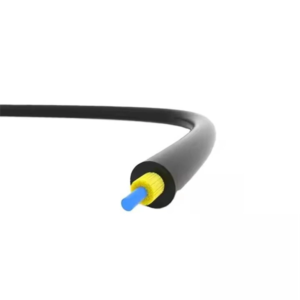
Its typical transmission distance is 20km or 40km. For instance, some ethernet switch manufacturers refer to the 1000BASE-LH SFP as the 1G 1310nm 40km SFP transceiver, which indicates the module's transmission distance and wavelength. The 10G SFP+ dual-fiber optical module is a small pluggable optical transceiver that adopts a dual-fiber bidirectional design. It completes signal transmission (Tx) and reception (Rx) through two independent optical fibers, ensuring the stability and reliability of signal transmission. An SFP (Small Form-factor Pluggable) module transmits data over fiber using specific wavelengths and power levels, which directly influence how far the signal can travel before degradation occurs. This is why two. If the optical module works at a wavelength near 850nm (880nm) or 910nm (940nm), then the module is a multi-mode fiber (MMF) optical transceiver, and if the working wavelength is 1310nm or 1550nm, it is a single-mode fiber (SMF)optical module. Generally, the maximum transmission distance(generally. The transmission distance of optical transceiver modules is divided into short distance, medium distance, and long distance. A 1-core module uses a single fiber core for data transmission, while a 2-core module uses two cores. o Think of a highway. Chromatic dispersion This is a key factor affecting single mode fiber distance.
[PDF]

An Optical Time Domain Reflectometer (OTDR) is a precision tool used to detect faults and measure loss along fiber optic links by analyzing backscattered light from high-speed pulses. Download the PDF of the datasheet for an overview of the product features, important specifications, and ordering information. We are the measurement insight company committed to performance, and compelled by possibilities. Tektronix designs and manufactures test and measurement solutions to break. OTDR testing analyzes fiber optic cable performance from end to end by testing components along the cable, including connection points, bends, and splices. What Is an OTDR? What Is an OTDR? An OTDR is a powerful tool that helps technicians and engineers assess the health of fiber optic cables. Essential for both installation and maintenance, OTDRs ensure network reliability with accurate fault location. An OTDR (Optical Time Domain Reflectometer) is a measuring instrument intended to measure the transmission loss and distance of optical fibers, locate cable cuts, and evaluate the connection loss and reflectance (return loss) of fusion splices, mechanical splices, connector connections, etc. Also. Time Domain Reflectometry (TDR) is a well-established technique for verifying the impedance and quality of signal paths in components, interconnects, and transmission lines. The OTDR enables field technicians to rapidly, reliably, and.
[PDF]

A constant trend in optical modules is to offer higher data rates within the size-limited and thermally-limited form factor by using smaller, integrated Power and Data-Converter solutions. The SFP module is a hot-pluggable optical transceiver used for connecting network switches. It converts electrical signals to optical signals and vice versa. For the 1G SFP module, it is primarily divided into the following two categories: Optical SFP Transceiver Optical transceiver connection RJ45. The optical module serves as a crucial component in optical fiber communication systems, operating at the physical layer, which is the lowest layer in the OSI model. An. Optical modules and media converters are both key photoelectric conversion devices widely used in fiber optic communication, data centers, enterprise networks, and broadband access systems. Many users are confused about their roles, differences, and connection rules. This article will clarify. Microwave photonics technology (MWP), which has been applied to various radar, Telcom, Electronic Warfare systems, is now facing more and more challenging development trend of miniaturization and modular array for increasing node counts and system complexity.
[PDF]
An optical module housing is the protective outer shell that encloses the internal components of an optical transceiver module. Optical modules (SFP, SFP+, QSFP) are small, but when multiplied by thousands of ports they become a meaningful line item in both energy and heat budgets. These modules are essential for converting electrical signals into light signals and vice versa, forming the backbone of fiber. However, when it comes to optical transceivers, cutting costs blindly can lead to compatibility issues, link failures, and unexpected downtime. So the real question is: 👉 How can you reduce optical module costs while maintaining reliability and performance? This guide breaks down practical. As an essential component of optical fiber communication, optical modules are optoelectronic devices that facilitate the conversion between optical and electrical signals during the transmission process. Operating at the physical layer of the OSI model, optical modules are core devices in optical. Optical modules are electronic devices that convert electrical signals into optical signals for transmitting data over an optical fiber. The internal structure of an optical module is complex but can be divided into several main parts.
[PDF]

This guide provides a complete framework for understanding, identifying, and planning MPO connector gender in data center environments. Visually, male and female MPO connectors are easy to distinguish: male connectors feature two alignment pins (PIN pins), while female connectors have corresponding holes instead of pins. An MPO connection is made between a male and female connector to make sure that there is proper alignment. Interfaces on active MPO equipment, such as transceivers are usually male, so any MPO trunk cable. In modern data centers and high-density fiber optic networks, MPO (Multi-Fiber Push-On) connectors have become an essential solution for achieving fast, reliable, and scalable connectivity. You will discover the physical distinctions between male and female connectors and how to develop a gender strategy for your infrastructure, which gender connects. Whether you're supporting parallel optics like 100G SR4 or densifying an optical distribution frame (ODF), MPO is now a cornerstone of network design. This article explains: And a practical checklist to design MPO systems that scale cleanly. If you only remember one thing: MPO is a multi-fiber. In MPO and MTP fiber connector systems, Male vs Female and Pin vs No-Pin describe the same core engineering attribute: the presence or absence of alignment pins on the MT ferrule. Unlike single-fiber connectors such as LC or SC, this distinction is not optional terminology but a mandatory.
[PDF]

Run the display transceiver [ interface interface-type interface-number | slot slot-id ] [ verbose ] command to view information about the optical module on a specified interface. In optical communication equipment, an optical module (Optical Module) contains several types of semiconductor chips that work together to complete the transmission and processing of optical signals. These chips typically include laser chips, photodetector chips, driver chips, transimpedance. When the optical module on an interface is faulty, you can run the display commands to view information about the optical module. Today, we will deeply analyze the four mainstream models of 100G QSFP28 dual-fiber optical modules: QSFP28-100G-SR4, QSFP28-100G-LR4, QSFP28-100G-ER4 and. The following uses the Moduletek SFP-10G-LR module connected to a Huawei S6700 switch as an example to introduce how to read information of the connected optical module on a Huawei switch. Figure 1 Schematic Diagram of Optical Module Connected to Switch 1. Optical Module Status Check Run the. Upgrade to 100G or 400G optics and save. Cisco Transceiver Modules - Learn product details such as features and benefits, as well as hardware and software specifications. Network administrators have a major challenge determining the right Cisco SFP modules, understanding complex model numbers that directly affect network performance and stability.
[PDF]
The CFP, short for C form-factor pluggable, is a multi-source agreement to define the form-factor of the optical transceiver for high-speed digital signal transmission. CFP transceivers are defined by CFP MSA to enable 40 Gb/s, 100 Gb/s and 400 Gb/s applications. The c stands for the Latin letter C used to express the number 100 (centum), since. What is a CFP optical module? Is it still relevant in 2026? And when should you choose it over newer alternatives? This guide is designed to answer those questions with clarity and technical depth. In this comprehensive article, we will delve into the world of CFP optical transceiver modules, exploring their. What is CFP Modules? Complete Guide to Standards, Variants, Comparisons, and Applications What is CFP Modules? Complete Guide to Standards, Variants, Comparisons, and Applications What is CFP Modules? Complete Guide to Standards, Variants, Comparisons, and Applications In the era of cloud. This article breaks down the key differences between CFP, CFP2, CFP4, and CFP8 optical transceivers commonly used in fiber optic networks. Figure 1: Dimensions of CFP, CFP2, CFP4, and CFP8 The table below summarizes the specifications of each form factor: 24 W (Max. ) In essence, the progression.
[PDF]

In the photopic region, luminous efficacy peaks at 683 lumens per watt at 555 nm. In fact, the lumen is defined in terms of the power at 555 nm (frequency of 540 × 1012 Hz). Luminous efficacy is defined as the luminous flux produced per unit of power, usually electrical power, measured in lumen per watt (lm/W). It is explained how the overall efficacy of a lighting installation is often lower than that of the light source itself due to factors like light absorption in. Luminous efficacy is a measure of how efficiently a light source produces visible light. Depending on context, the power can be either the radiant flux of the source's output, or it can. The relative spectral responsivity of the human visual system was first defined by the Commission Internationale de l'Éclairage (CIE, the International Commission on Illumination) in 1924. The response of the eye as a function of frequency is called the luminous efficacy of the eye. It has been tabulated for both the light-adapted (photopic) case and the dark-adapted (scotopic) case. Source: Table 6-1 of.
[PDF]

Average Optical Power: How bright the light is (measured in dBm). Too dim? Your signal gets lost in the fiber. Extinction Ratio: The difference between “on” (1) and “off” (0) light power. A higher ratio = cleaner signals. Transmitter Side: An electrical signal hits a laser diode (LD) or LED, which spits out light. Receiver Side: Light enters a photodetector (like a tiny solar cell), which turns it back into electricity. A built-in amplifier boosts the signal for your. The average transmitted optical power refers to the optical power output by the light source at the transmitting end of the optical module under normal working conditions, which can be understood as the intensity of light. In communication, we usually use dBm to represent optical power. However, in practical use, we adopt the average Tx power. The transmission power is related to the. This article provides an in-depth analysis of two key performance indicators of optical modules: transmitter power and receiver sensitivity. Transmitter power characterizes the average optical power output from the laser under rated conditions, while receiver sensitivity indicates the minimum. An optical module is a connecting module that serves as an optical-electrical conversion device. At the receiver end, the optical signals are reconverted into electrical.
[PDF]

Learn how to monitor SFP optical power on Cisco switches, interpret Tx/Rx levels, and troubleshoot fiber link issues. Step-by-step CLI commands, model-specific guidance, and best practices included. In this article, we will break down the key factors influencing TX/RX power, explain how to calculate the optical power budget, and provide actionable insights for optimizing your network's performance using SFP modules. SFP (Small Form-Factor Pluggable) modules are compact transceivers that allow. SFP (Small Form-factor Pluggable) optical modules are compact, hot-pluggable transceivers that enable network equipment to connect seamlessly to fiber and copper links. Even if an interface appears up, degraded Tx/Rx levels can cause intermittent flapping, packet loss, or err-disabled states. Think of it as the “translator” for your network equipment, converting electrical signals into optical signals. The most two important factors of the SFP transceiver: Output power (TX power) and receiver sensitivity (RX sensitivity). The optical TX power is the signal level leaving from that device, which should be within the transmitter power range. The RX sensitivity is the incoming signal level being. In current network communication, SFP optical modules are an indispensable physical foundation for building network channels. They form high-speed channels for optical signal transmission. Therefore, to ensure their.
[PDF]

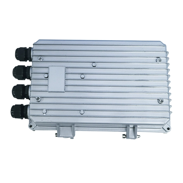
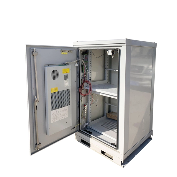
Usually, the 10G/25G grey light optical modules with a short transmission distance are applied for connecting AAU/DU with WDM/OTN/SPN. The connections between WDM/OTN/SPN network devices can be achieved by 10G/25G/50G/100G dual-fiber or single-fiber bidirectional. Compared with Draft A (2013-07-30), this issue includes the following new topic: 2. This section describes engineering specifications of an AAU, including input power and equipment specifications. 7. In 2/3/4G networks, 10Gbps optical modules are generally enough for CPRI interfaces. In 5G networks, CPRI is also upgraded to eCPRI. Currently, 5G of the bearer network mainly uses 25Gbps optical modules. Next, ETU-LINK will introduce the types of optical modules used by 10G SFP+ and 25G SFP28. What is the difference between the 5G bearer network and the traditional optical transmission network? The main difference is that 5G fronthaul needs to support CPRI/eCPRI protocol. Most of the AAU of 5G base stations are deployed outdoors. In order to resist harsh environments such as high. The optical modules used to connect BBU and RRU devices are optical modules and optical fibers. Product Versions The following table lists the product versions related to this document. 25G SFP optical module adopts the wavelength of 850nm, with an operating.
[PDF]

Run the following command to view detailed optical module information on the device interface: display transceiver interface <interface-type> <interface-number> verbose The command output is divided into two parts:. Run the following command to view detailed optical module information on the device interface: display transceiver interface <interface-type> <interface-number> verbose The command output is divided into two parts:. When the optical module on an interface is faulty, you can run the display commands to view information about the optical module. Related Information Video Identify a Huawei-Certified Optical Module Run the display transceiver [ interface interface-type interface-number | slot slot-id ] [ verbose ]. During use, reading optical module information helps understand its real-time operating status, enabling faster troubleshooting of link abnormalities. The following uses the Moduletek SFP-10G-LR module connected to a Huawei S6700 switch as an example to introduce how to read information of the. See the interface module via the optical display command information, including general information of the optical module, manufacturing information, and alarm information. If it is not a Huawei-certified optical module, replace it with a Huawei-certified optical module. If the optical module is installed on a GE port, run the display interfaceGigabitEthernet x/x/x command to view port information when the optical module.
[PDF]

Uses 12 wavelengths derived by shifting 6 traditional CWDM wavelengths left and right (±3. 5nm) using temperature tuning. Balances cost and channel density. Applications: Primarily 5G mobile fronthaul and midhaul networks requiring moderate capacity and cost efficiency. In fiber-optic communications, wavelength-division multiplexing (WDM) is a technology which multiplexes a number of optical carrier signals onto a single optical fiber by using different wavelengths (i., colors) of laser light. This technique enables bidirectional communications over a. This is the complete guide to Dense Wavelength-Division Multiplexing (DWDM) wavelengths and channels in 2024. Then, you will enjoy this new complete DWDM wavelength channels guide. What are the benefits of DWDM? #3. DWDM and CWDM enable carriers to deliver more services over their existing fiber infrastructure by combining multiple wavelengths on a single fiber. But navigating the alphabet soup of CWDM, DWDM, MWDM, LWDM, and SWDM can be daunting. 5 nm (800 GHz) in the O-band of 1270–1330 nm by using x-cut lithium-niobate-on-insulator (LNOI) photonic waveguides for the first time.
[PDF]