00 Original price was: $285. Add an LC fiber optic connection to your Blackmagic Studio Camera, Teranex Converter, ATEM hardware, or any other professional device that supports SFP cages with. Help others learn more about this product by uploading a video! Looking for specific info? Would you like to tell us about a lower price? Found a lower price? Let us know. Although we can't match every price reported, we'll use your feedback to ensure that our prices remain competitive. 6G data rates support SD, HD, and 4K resolutions, and the fiber optic communication allows. FiberMall SFP+ Transceivers are hot swapping, cost effective modules supporting data rate of 6Gbps/8Gbps/10Gbps/16Gbps/32Gbps and up to 120km transmission. Learn more Spread the cost of your purchases over 3 to 24 months with an interest rate from 0. There's no fees if you pay on time. All set! You can manage payments in the Klarna app or website Down payment may be required. Klarna Monthly.
[PDF]
This manual describes Inspect, a command-line tool for debugging TNS C/C++, COBOL, FORTRAN, Pascal, Screen COBOL, and TAL programs and snapshots on HP NonStopTM TNS/R and TNS/E systems. MFT (Mellanox/NVIDIA Firmware Tools) is a set of firmware management utilities for querying firmware details, performing firmware upgrades, and other configuration tasks. It includes four main components: mst, mlxburn, flint, and Debug Utilities. For full specifications, refer to the official. All commands were tested on HP/Aruba 5400 switches (specifically 5406Rzl2), but will work on any model with recent firmware versions (16. x or newer), except for the hardware features unavailable on smaller models, like VSF. This publication supports J06. 03 and all subsequent J-series RVUs, H06. Show general info: current CPU load, uptime, memory used/free, software. The HP 1-Port 1GbE Flex IO NIC is designed to work in the Flex IO port of select HP systems. Refer to platform specifications for compatibility. It utilizes a Realtek RTL8153 10/100/1000 Ethernet controller to provide an additional 1GbE LAN Port. 3az-2010, also known as Energy. HPE Insight Diagnostics is a hardware diagnostic tool. To start iLO with keyboard and monitor connected to the box - press F8 while booting Invoke virtual serial port. Starting text console. Press 'ESC (' to return to the CLI Session.
[PDF]

Usually, the 10G/25G grey light optical modules with a short transmission distance are applied for connecting AAU/DU with WDM/OTN/SPN. The connections between WDM/OTN/SPN network devices can be achieved by 10G/25G/50G/100G dual-fiber or single-fiber bidirectional. Compared with Draft A (2013-07-30), this issue includes the following new topic: 2. This section describes engineering specifications of an AAU, including input power and equipment specifications. 7. In 2/3/4G networks, 10Gbps optical modules are generally enough for CPRI interfaces. In 5G networks, CPRI is also upgraded to eCPRI. Currently, 5G of the bearer network mainly uses 25Gbps optical modules. Next, ETU-LINK will introduce the types of optical modules used by 10G SFP+ and 25G SFP28. What is the difference between the 5G bearer network and the traditional optical transmission network? The main difference is that 5G fronthaul needs to support CPRI/eCPRI protocol. Most of the AAU of 5G base stations are deployed outdoors. In order to resist harsh environments such as high. The optical modules used to connect BBU and RRU devices are optical modules and optical fibers. Product Versions The following table lists the product versions related to this document. 25G SFP optical module adopts the wavelength of 850nm, with an operating.
[PDF]

This guide provides a fully updated and industry-ready overview of LC fiber optics, explaining the origin and design of LC connectors, their key features, and the complete ecosystem of LC-based products used in modern networking. It covers LC connectors, LC patch cables, uniboot designs, armored. LC stands for Lucent Connector (also colloquially “Little Connector”). It was introduced by Lucent Technologies to deliver small form factor (SFF) optical connections that match the density of RJ-45 copper ports. 25 mm ferrule (half the size of SC's 2. 5 mm) enables twice the port. Fiber optic connectors are used to the mechanical and optical means for cross connecting fibers. Fiber optic connectors can also be used to join fiber cables to transmitters or receivers. As a small-form-factor (SFF) interface, LC has become the default duplex connector in enterprise LANs, telco closets, and data-center topologies because it balances density, repeatability, and cost. SC connectors were originally designed for FTTH, but they were gradually popularized and used on a large scale due to their small size and convenience. You may find LC connector has a strong family which includes but not limited to LC optical fiber connectors, LC fiber patch cables, LC fiber.
[PDF]

In this tutorial video, we will show you step-by-step how to safely and effectively remove an optocoupler from a circuit board using desoldering wick. We will walk you through the tools you will need, the proper technique for using the desoldering wick, and the precautions to take to av. more In. Whether you're replacing a faulty component, salvaging parts from an old board, or correcting a soldering mistake, knowing how to desolder effectively is essential. This guide will walk you through the tools, techniques, and best practices for desoldering components from a circuit board safely and. Desoldering is a process that removes the solder and components from a printed circuit board or any other type of electronic assembly. This is a meticulous process and it can easily damage the board, or the components, if not properly done. Thus, it is important to know how to desolder properly. If you're desoldering a battery from a circuit board, use flush cutters to cut each wire one-at-a-time to isolate the battery before you desolder the wires. Whenever possible, create an indirect path by soldering connectors onto the battery and the circuit board. This reduces the chance of an. Sorry, an unexpected error has occurred. Why Publish? The Ultimate Guide to Desoldering: From using desoldering irons to sketchily knocking breadboard components off on the side of a table, there are tons of ways to remove components from a circuit board.
[PDF]

It involves encapsulating the optical chip in a metal box filled with inert gas (usually helium) to protect the optical elements from external environmental influences and enhance heat dissipation. COB, BOX, and TO-CAN packaging each offer unique advantages tailored to specific applications. COB packaging integrates components directly onto a PCB, enabling miniaturization and cost efficiency. BOX packaging seals optical chips in a metal enclosure with inert gas, ensuring long-term stability. The COB process refers to a technology that directly mounts bare chips onto a printed circuit board (PCB), connects them via gold wire bonding, and then encapsulates and protects the chips and wires using organic adhesive. Compared with conventional processes, the COB process offers high packaging. Box, COB, and TO can are currently the most prevalent packaging forms for optical components. Box packaging, also known as hermetic sealing, has a long history. Common optical device packaging methods include COB (chip-on-board packaging), BOX and coaxial packaging. What is COB technology? COB (Chip on board) is a form of packaging that directly bonds the. The invention provides an SFP28 SR optical module structure of a COB process, and belongs to the field of optical module structures. The micro-optical module comprises a shell, an unlocking mechanism, an EMI shielding structure, a circuit board, a micro-optical module arranged at one end of the.
[PDF]
The SFP-10G-ER transceiver module is the proven, standards-based workhorse for extending 10 Gigabit Ethernet up to 40km over cost-effective single-mode fiber. This hot-pluggable SFP+ transceiver is engineered to transmit 10Gbps data streams over single-mode fiber (SMF) for link lengths up to 40 kilometers, making it indispensable for metro Ethernet, campus backbone networks, enterprise data center interconnects (DCIs), and telecom access networks. 10GBASE-LR SFP+ Module: 10Gb/s data rate, Single-Mode, duplex LC connector, 1310nm wavelength, the transmission distance up to 10km, working temperature: 0℃ ~ 70℃, Tx Power (dBm): -6. Equipped with an LC connector. Experience reliable high-speed networking with the VIVOTEK SFP-2000-SM13-10, a 10 Gigabit Mini GBIC designed for enhanced performance. Utilizing 10GBase-X technology, it delivers data transfer speeds up to 10 Gbps over compatible cables, ensuring efficient and scalable connectivity. This module. The 10 Gigabit Singlemode SFP+ Transceivers provide high-performance, reliable connectivity for modern 10 Gigabit Ethernet (10GbE) networks. These transceivers are designed for singlemode fiber, offering superior performance over long distances. Whether you're working on data centers, campus. These SFP transceiver modules come in a metal housing that reduces electromagnetic interference and increases their durability.
[PDF]

These general purpose fiber clamps provide easy means for incorporating glass or plastic optical fibers into optomechanical post assemblies or SM1-threaded components. The precision V-groove and rubber pad are designed to clamp onto the buffer of single mode or multimode fibers without damaging. Harwin supplies a range of surface-mount shield can clips to provide a straight-forward, easy-to-use board-level shielding solution. The combination of SMT clips with a shield can provides a simple and cost-effective method of shielding vulnerable or EMI-radiating board components. Harwin's shield. Check each product page for other buying options. 2-piece kit Fiber optical thermal stripper M8 & fiber optical cleaning clip compatible with bare fiber/bundle and ribbon fiber for 1-48 core dual heating mode and 8-level temperature regulation. Need help?. FPH Fiber Chucks and Holders are designed to terminate bare optical fibers and provide precise coupling and mounting within optical systems. Compatible strain relief boots and fiber clamps are also available. Clamps are larger than clips and designed to hold multiple cables and wires together. Blind plugs are used to close. 1-800-363-1992 Have any questions? Talk with us directly using LiveChat.
[PDF]

An optical module's actual transmit power measured by an optical power meter is lower than the nominal transmit power of the power module. The possible causes are: Bores of the optical module are contaminated. Stable optical power is the foundation of every high-capacity optical transport system. Even minor deviations—whether too high, too low, or unstable—can impact signal integrity, trigger service alarms, or interrupt traffic on DWDM, OTN, or long-haul optical line systems. This is the domain of Cell-to-Module (CTM) power loss, a series of. This paper reviews methods for reducing different optical and electrical loss mechanisms in PV modules and for increasing the optical gains in order to achieve higher CTM ratios. Various solutions for optimizing PV modules by means of simulations and experimental prototypes are recommended. Have you ever experienced an unexpected network outage due to the failure of an SFP/SFP+ optical transceiver? Network outages can bring your ability to communicate and work to a halt, and your IT team will likely be frantically looking for a solution. It is important to understand how to. This article provides an in-depth analysis of two key performance indicators of optical modules: transmitter power and receiver sensitivity. Transmitter power characterizes the average optical power output from the laser under rated conditions, while receiver sensitivity indicates the minimum.
[PDF]

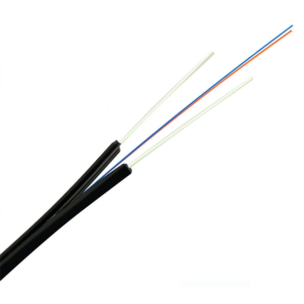
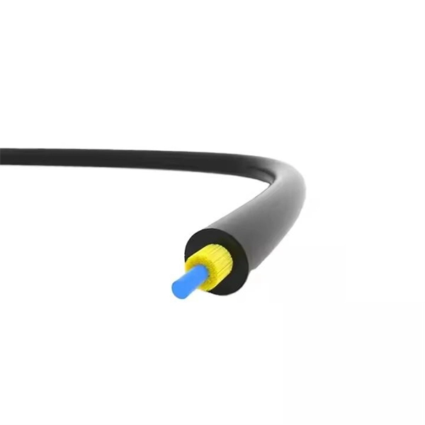
Its typical transmission distance is 20km or 40km. For instance, some ethernet switch manufacturers refer to the 1000BASE-LH SFP as the 1G 1310nm 40km SFP transceiver, which indicates the module's transmission distance and wavelength. The 10G SFP+ dual-fiber optical module is a small pluggable optical transceiver that adopts a dual-fiber bidirectional design. It completes signal transmission (Tx) and reception (Rx) through two independent optical fibers, ensuring the stability and reliability of signal transmission. An SFP (Small Form-factor Pluggable) module transmits data over fiber using specific wavelengths and power levels, which directly influence how far the signal can travel before degradation occurs. This is why two. If the optical module works at a wavelength near 850nm (880nm) or 910nm (940nm), then the module is a multi-mode fiber (MMF) optical transceiver, and if the working wavelength is 1310nm or 1550nm, it is a single-mode fiber (SMF)optical module. Generally, the maximum transmission distance(generally. The transmission distance of optical transceiver modules is divided into short distance, medium distance, and long distance. A 1-core module uses a single fiber core for data transmission, while a 2-core module uses two cores. o Think of a highway. Chromatic dispersion This is a key factor affecting single mode fiber distance.
[PDF]

This guide provides a clear, step-by-step explanation of how to install an SFP module correctly, based on real-world deployment practices. The fastest way to do so is by unplugging the power plug from the power outlet. This is a Class A product. In a domestic environment, this product might cause radio interference in which case the user might be required to take adequate measures Electric shock hazard. This equipment is to be. This Quick Guide covers the model: CCR2004-16G-2S+PC. You can find the product model name on the case label (ID). Or scan the QR code with your mobile phone. lv/um The most important. The Installation of the equipment must comply with local and national electrical codes. Please read the mounting instructions carefully before beginning installation. Failure to use the correct hardware or to follow the correct procedures. The CCR2004 is a high-performance multicore router with twelve 10G SFP+ ports and two 25G SFP28 ports. Before you work on any equipment, be aware of the hazards involved with electrical circuitry, and be familiar with standard practices for preventing accidents. It covers critical preparation checks, proper insertion techniques, hot-swap and safety considerations, common installation mistakes, and practical. The Cisco 8000 series routers support both ZR and ZR+ modules. The Cisco 8200 Series uses a single Cisco Silicon One ASIC to deliver full routing functionality. These fixed port, high-density routers provide 10.
[PDF]
The CFP, short for C form-factor pluggable, is a multi-source agreement to define the form-factor of the optical transceiver for high-speed digital signal transmission. CFP transceivers are defined by CFP MSA to enable 40 Gb/s, 100 Gb/s and 400 Gb/s applications. The c stands for the Latin letter C used to express the number 100 (centum), since. What is a CFP optical module? Is it still relevant in 2026? And when should you choose it over newer alternatives? This guide is designed to answer those questions with clarity and technical depth. In this comprehensive article, we will delve into the world of CFP optical transceiver modules, exploring their. What is CFP Modules? Complete Guide to Standards, Variants, Comparisons, and Applications What is CFP Modules? Complete Guide to Standards, Variants, Comparisons, and Applications What is CFP Modules? Complete Guide to Standards, Variants, Comparisons, and Applications In the era of cloud. This article breaks down the key differences between CFP, CFP2, CFP4, and CFP8 optical transceivers commonly used in fiber optic networks. Figure 1: Dimensions of CFP, CFP2, CFP4, and CFP8 The table below summarizes the specifications of each form factor: 24 W (Max. ) In essence, the progression.
[PDF]
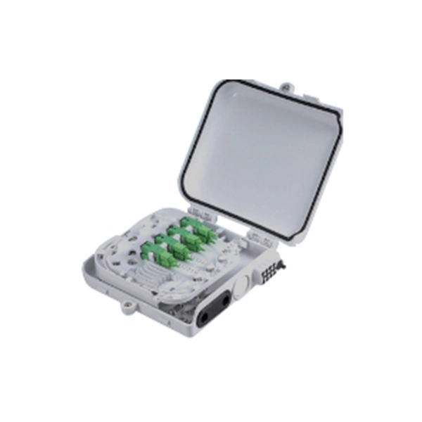
A passive optical network (PON) is a point-to-multipoint fiber network architecture that uses optical splitters to deliver high-bandwidth services from a single fiber to multiple end users without requiring active electronics in the field. While there are many subtle differences, a clear distinction between active optical networking and PON topology is PON's use of a. A passive optical network (PON) is a fiber-optic telecommunications network that uses only unpowered devices to carry signals, as opposed to electronic equipment. In practice, PONs are typically used for the last mile between Internet service providers (ISP) and their customers. In this use, a PON. A passive optical network sends data as light through fiber cables. You get internet, TV, and phone services with fewer cables and no powered splitters between you and your provider. What equipment do you need for PON at home? You need an optical network unit (ONU) at your home. By eliminating powered components between the service. Technology drives the broader adoption of passive optical LAN (also known as a passive optical local area network) across various sectors. Not having a long history as a passive optical network (PON), it is a better replacement for copper-based LANs in local area networks. This article covers every.
[PDF]

As illustrated in typical SFP internal structure diagrams, the module's core components include an optical transmitter assembly (TOSA), laser driver, optical receiver assembly (ROSA)—some high-sensitivity modules (like L16. 2) use APD receivers, which require an additional booster. The optical module serves as a crucial component in optical fiber communication systems, operating at the physical layer, which is the lowest layer in the OSI model. Its primary function is to achieve optoelectronic conversion by converting electrical signals into optical signals and vice versa. Among various optical module form factors, SFP (Small Form-Factor Pluggable). The function of the optical module is to carry out the photoelectric and electro-optic conversion. In this article, ETU-LINK will introduce to you what are the core components of the optical module? 1. TOSA: Its main function is to convert electrical signals to optical. the embodiments of the present applicationprovide an optical emission module, an emission device, a detection device and a terminal, which can improve the energy density of a light spot formed by an emission light beam and improve the integration of the device. an embodiment of the present.
[PDF]

This comprehensive guide breaks down the internal structure, core components (TOSA, ROSA, lasers), and operational mechanisms of SFP optical modules, enriched with technical insights and real-world applications. SFP (Small Form-factor Pluggable) optical modules are compact, hot-pluggable transceivers that enable network equipment to connect seamlessly to fiber and copper links. As a leading provider of optical communication solutions, Weunion integrates these. One vital element in the data communication sector is the Small Form-factor Pluggable (SFP) module. In this blog, we will explore the inner workings of these modules, with a particular focus on three essential optical components: TOSA, ROSA, and BOSA. SFP modules are small, hot-swappable devices. Optical modules are devices used to connect network devices, transmit and receive data between network devices, and can be used to convert optical and electrical signals. The optical module is a very important component in an optical communication system. Think of it as the “translator” for your network equipment, converting electrical signals into optical signals. available with a variety of types of copper SFP and fiber SFPs, SFP+. This transceiver module is compliant wi h the small form-factor pluggable (SFP) multi-source agreement (MSA). They industrial performance with an extended operating temperature range. Through real-time monitoring, the DDM.
[PDF]
