The distribution box is a crucial piece of equipment that connects solar panels to the AC power grid. Solar energy is a clean, renewable, and pollution-free source. A Solar Distribution Box plays a critical role in managing, controlling, and distributing electrical power safely within solar systems. Without it, the risk of electrical faults, system failures, and energy loss increases significantly. As solar adoption continues to rise globally, understanding. A panel junction box is typically mounted on the back of a solar module. It serves as the module's protected connection point—housing internal electrical terminations and enabling safe, standardized external connections via connectors. A PV combiner box is installed at the system level. Its primary. In modern solar PV installations, multiple strings of solar panels generate direct current (DC) power that must be safely consolidated, routed, and protected before it reaches the inverter. Handling high-voltage DC electricity requires precision and uncompromised safety measures. This essential device incorporates sophisticated protection mechanisms and monitoring capabilities to ensure.
[PDF]

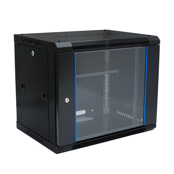
Professional installation available nationwide across the Philippines. 100% genuine products from authorized distributors with full warranties Free delivery to major cities, professional installation available Technical support and consultation from certified solar engineers. Professional installation available nationwide across the Philippines. Buying Distribution Box For Solar Set Up with great prices online? Nasa Lazada Yan! The top online shopping platform in the Philippines always boasts a great assortment. Get a ₱50 voucher if your order arrives late. IP65 design, waterproof, anti dust and anti ultraviolet. Strict test for high and low temperature, used widely. The simple installation, the simplified system wiring, the convenient wiring. Used for single crystal silicon solar modules, polycrystalline. In Metro Manila, the continuous rise of commercial high-rises, BPO (Business Process Outsourcing) centers, and mixed-use developments in areas like Bonifacio Global City (BGC) and Makati requires robust and highly reliable electrical distribution networks to ensure zero downtime. On the industrial. Premium solar panels, inverters, and components from trusted international brands. They offer a range of services, including the development of solar farms and grid-tied rooftop. Sale! © 2026 Solar Hub PH.
[PDF]

This whitepaper describes the various communications technologies while describing the inherent limitations and advantages. Off-grid communication systems, powered by sustainable energy sources like solar, enable vital connectivity in remote locations, during emergencies, and for operations requiring autonomous communication capabilities. From remote European mountain refuges to industrial facilities operating in. Introduction: Free Space Optics (FSO) is a wireless optical technology that transmits data via laser beams. It leverages light waves to transmit and receive data in a Line-of-Sight (LOS) path between buildings. Unlike Optical Fiber Cable (OFC), FSO uses air as the medium for data transportation. Solar powered communication systems, harnessing the sun's energy to power various communication devices and networks, represent a significant step towards achieving this goal. This essay will explore the diverse applications, benefits, challenges, and future prospects of these systems. This paper aims to explore the FSO system, analyze previous research, and discuss the challenges associated. Solar light communication is a technology that utilizes light emitted from solar-powered sources to transmit information. Employs modulation techniques to encode data within light signals, 3. Low Noise Amplifiers (LNAs) are a key component in many electronic systems and communication devices. These critical elements are used extensively to amplify.
[PDF]
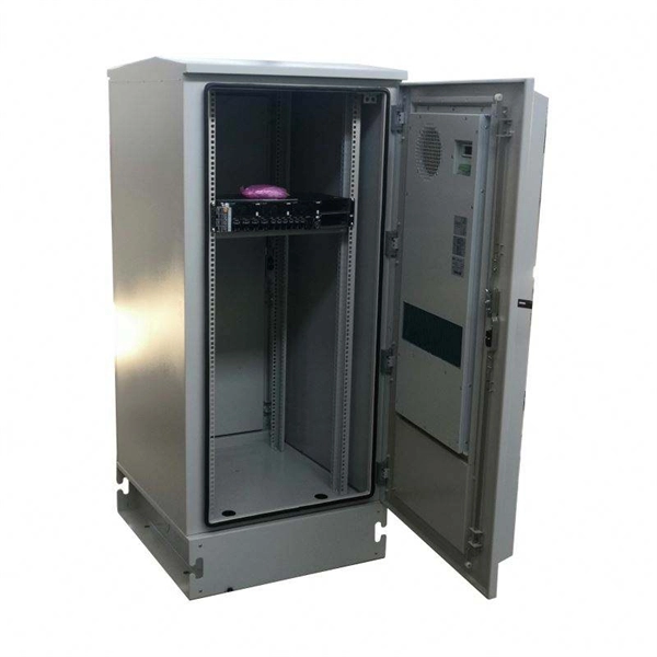
Secondary distribution boxes, also known as sub-distribution boxes, generally serve specific power supply areas. These boxes have inner and outer doors, powder-coated exteriors, and are designed for safety and aesthetic appeal, with rainproof tops for outdoor work. From the transformer's low-voltage side (0. 4kV), power is distributed to a main distribution panel (primary distribution box). From there, it is routed to individual building distribution boxes (secondary distribution boxes), which subsequently supply power to unit-level distribution boxes. Primary distribution systems consist of feeders that deliver power from distribution substations to distribution transformers. Many feeders leave substation in a concrete ducts and are routed to a nearby pole. Safe and beautiful, waterproof box top suitable for field work. It is specially designed for the special situation of the project construction site and meets the relevant construction power specifications and standards of the. Understanding the fundamental distinction between Primary and Secondary distribution in electrical systems is pivotal for designing efficient and reliable electrical distribution systems tailored to specific needs across various domains. Primary Distribution: Involves the transmission of high.
[PDF]
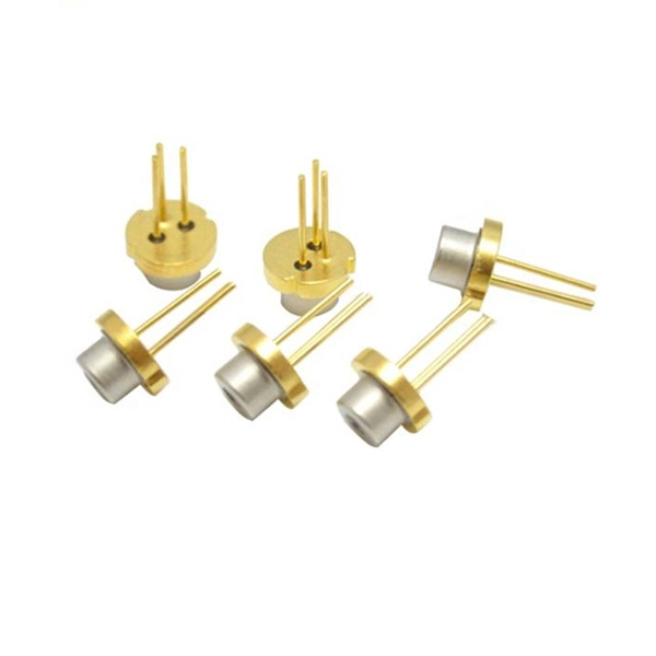
The LS-SM3101-20C SFP transceivers are high performance, cost effective modules supporting data rate of 125Mbps/155Mbps and 20km transmission distance with SMF. The transceiver consists of three sections: a Cooled EML laser transmitter, a APD photodiode integrated with a trans-impedance preamplifier (TIA). The AFCT-5745NPZ/UPZ Lead-free Singlemode Optical Transceivers have been qualified in accordance to the requirement of Telcordia Document GR-468-CORE under the supervision of Avago Technologies Quality & Reliabil-ity Department. This report summarizes the qualification tests over a range of. Copyright © 2022 GOC-UZ. See our terms of use and privacy policy. Volza's Solution gives you 100x return in Six Months! Use strategic filters to explore Optical transceiver module Import data like a seasoned analyst, uncovering hidden opportunities in the Optical transceiver module import business. Our database includes 321 Import shipments, involving 63 Buyers. Up to now, MEISU has developed various high-temperature resistant optical devices not only with regular SM fiber, but also with PM fiber array by applying special high-temperature coating to the normal PM fiber, providing muiltiple choices for silicon photonic (SiPh) solder reflowable assembly at.
[PDF]
A switch must use optical or copper modules that have been certified for use on Huawei switches. Non-certified optical or copper modules cannot ensure transmission reliability and may affect service stability. Huawei is not liable for any problem caused by the use of non-certified optical or copper. The purchased products, services and features are stipulated by the contract made between Huawei and the customer. Unless otherwise specified in the contract, all. Compatible SFP transceiver supports up to 80km link lengths over single-mode fiber (SMF) using a wavelength of 1550nm via an LC connector. Each SFP transceiver module is individually tested to be used on a series of Cisco switches, routers, servers, network interface card (NICs) etc. It has minimum guaranteed optical budget of 25 dB, with in most cases is enough to reach about 40 km distance. However, distance is. We supply professional-grade optical networking components for ISPs, enterprises, data centers, and network installers across Kenya, and the Authentic Huawei 155M-1310nm-15km-SM-eSFP is a proven and trusted solution for reliable fiber connectivity. Huawei is globally recognized for its advanced. Introducing the Huawei OSC015B01, a cutting-edge optical transceiver designed for high efficiency and unparalleled performance. This eSFP module, with its Tx 1310nm/Rx 1550nm wavelength capabilities, is engineered for 155M operations, making it ideal for a variety of network enhancement tasks.
[PDF]

BBU end can be connected to CWDM coarse wavelength division multiplexer through CWDM color optical module and OS2 single mode optical fiber patch cord, and then transmitted to CWDM coarse wavelength division multiplexer with one or two optical fibers. The operation of base stations requires a large number of optical modules for interconnection between devices, and we will talk about the application of optical modules in mobile communication base stations. Communication base station is composed of machine room, base station, antenna, feeder. The base station can be divided into two modules: the RRU for transmitting signals and the BBU for processing signals. The BBU is small and exquisite, with low power consumption, while the RRU is large and has high power consumption. In 4G networks, the optical modules used to connect BBU and RRU are mainly gigabit to 10Gbit optical modules. In modern server racks, the wrong optical choice can silently tax performance: queues grow, link training becomes flaky, and operators end up swapping modules mid-quarter. In 5G networks, CPRI is also upgraded to eCPRI. Currently, 5G of the bearer network mainly uses 25Gbps optical.
[PDF]
A cooker is an essential thing for every kitchen, and you can built it into your kitchen island or just place it between the parts of the kitchen island. Another idea is buy just a minimal cook top, it will be easi.
[PDF]

This helps keep fiber optic cables safe from harm and signal problems when you put them in. Use the right lubricant. Follow the rules for tension and bend radius. Try new methods like air blowing. Use smart. Fiber optic cable is surprisingly strong, durable and pliable; however, several best practices should be followed to ensure a successful cable installation. This article explores recommendations for pulling and installing fiber optic cable. This makes sure the cable pull is smooth and safe. Use smart monitoring devices. The Future Ready Solutions Tools & Test. A duct is available from point A to point B, a pull tape is blown in, a fiber optic cable is attached to it and the cable is pulled through the duct. Sounds simple, doesn't it. Recent observations and conversations with more than a few people in the fiber optic business have indicated. Route plan to ensure the duct run maintains the minimum bend diameter of the cable. For more information and all recommendations for installation, refer to Corning Optical Communications Standard Recommended Procedure SRP 005-011, "Duct Installation of Fiber Optic Cable". more Route plan to ensure.
[PDF]
Picking up the best router for fiber internet isn't just about going to the market and choosing one of the best wireless routers. Instead, you need to carefully look at its specs, performance, and the type of securit.
[PDF]

Get answers to frequently asked questions about broadband services at BTC Bahamas. At Lightcommunication Company, we specialize in comprehensive fiber optic solutions, ensuring superior connectivity through expert services in installation, splicing, and network maintenance. We strive to revolutionize communication by providing cutting-edge fiber optic services that empower. BTC, also known as the Bahamas Telecommunications Company, is the national telecommunications company of the Bahamas. It offers a range of internet services, including fibre optic and DSL connections, and has a wide network of fibre optic cables, allowing it to provide high-speed internet to both. Clear Fiber Technology Solutions is a leading and reputable Telecommunications Contracting and Consulting Firm serving the Bahamas and Caribbean area. We understand the importance of Professional and Reliable Communications Services. We take a comprehensive approach to secure solutions, providing. Our aim is to provide reliable, cost effective, comprehensive solutions with efficient service to assist you in building I. infrastructure you can depend on. We want to be your partner of choice. call on us when you need to build out, upgrade or expand. Along the way we make it our mission to enrich lives and businesses through reliable, fast and future ready technology. Cable Bahamas nurtures education, wellness and cultural growth through dedicated partnerships and.
[PDF]

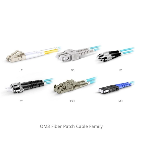
Connecting a multi-mode SFP to single-mode fiber creates a major signal mismatch. A small portion of the transmitted light gets captured. This leads to high attenuation and frequent link drops. I suggest you avoid such setups. Use them if essential and with proper mode. A Fiber Channel SFP is a specialized optical transceiver designed exclusively for Fiber Channel (FC) networks, enabling high-speed, low-latency, and lossless data transmission in Storage Area Network (SAN) environments. These transceivers comply with the ANSI INCITS 404-2005 Fiber Channel standard and IEEE 802. 3 for. There are two main types of fiber optic cables: single mode and multimode. Although they can do the same job in some instances, the different construction methods make each of them better suited to certain tasks and budgets. That makes picking between single mode and multimode fiber optic cables an. Single-mode (SMF) and multi-mode fiber (MMF) use different core sizes, sources and wavelengths. Understanding the compatibility constraints prevents costly downtime and troubleshooting. What Is the Difference Between Single Mode and Multimode Fiber? The main difference between these fiber options comes down to how light travels through. What is Single-mode SFP? Before we compare them, we need to know their brief definitions. A single-mode SFP is specially used with the 9/125µm single-mode fiber (SMF) but can not be used with multimode fiber cable.
[PDF]

Used for hoisting cable trays under I-beams and U-shaped steel. Likely used for specific horizontal support. L-shaped metal profile for support or connection. Various customized brackets made from angle iron. When developing our cable support OBO can offer reliable solutions for systems, three attributes are at the routing and fastening cables securely core of what we do: efficiency, resil- for each of these installation challeng-ience and safety. es in the industrial environment. Our cable support. An electrical cable tray system serves as a rigid structural raceway designed to support and route electrical cables and wires. Unlike a simple wire trough, which is typically a covered channel for shorter runs, cable trays provide a comprehensive support system for complex wiring paths over long. This publication is intended as a practical guide for the proper and safe* installation of cable ladder systems, cable tray systems, channel support systems and associated supports. Cable ladder systems and cable tray systems shall be manufactured in accordance with BS EN 61537, channel support. maintain spacing or to keep cables in place when the tray is ect the minimum bend ra-dius for cables as they exit the bottom of the cable tray. These guidelines are not intended to cover all details or variations in cable ladder and cable tray.
[PDF]

Designed specifically for deployment alongside power lines and utility poles, ADSS eliminates the need for metallic components and external support structures, making it a go-to choice for power grid communications, smart cities, and rural connectivity. AFL-ADSS® (All-Dielectric Self-Supporting) fiber optic cable is a non-metallic cable which supports its own weight without the use of lashing wires or messenger cables. We offer a wide range of options, from 6 fibers to 144 fibers, all the way up to 432 fibers and even 6904 fibers, which are. In the realm of aerial fiber optic infrastructure—where cables must withstand harsh weather, high voltages, and mechanical stress— ADSS (All Dielectric Self-Supporting) fiber optic cables stand out as a game-changer. However, choosing the right ADSS cable can be overwhelming due to the variety of types and specifications available. ADSS fiber cable is used by electrical utility companies as a communications medium, installed along existing overhead. Discover the latest ADSS fiber optic cable prices for various spans and core counts. Get competitive quotes, understand cost factors, and choose the best solution for your aerial fiber project. As global demand for faster and more reliable broadband expands, ADSS (All-Dielectric Self-Supporting).
[PDF]
An improper cleaving angle can lead to uneven fibre surfaces, which makes it difficult for the fusion splicer to align the fibres. The cleaver should produce a perpendicular cut to the fibre to ensure proper alignment during splicing. Poor cleaving is one of the most common causes of poor splice results when using a fusion splicer. When cleaving isn't done correctly, it can lead to gaps, misalignment, or even an incomplete splice, which can compromise the integrity of your network. But fear not; there are simple troubleshooting. The performance of a fiber optic splice is determined by a number of factors, including the quality of the fiber, the cleanliness of the splice, and the techniques used to make the splice. Intrinsic factors, such as the refractive index of the fiber, are those that are inherent to the fiber itself. To counteract these errors, technicians can go through the following troubleshooting checklists: Perform an Arc Test: Before splicing, it's important to perform. One of the most frequent complaints among technicians is unexpectedly high splice loss. The root causes typically include: To resolve this, first. The fiber diameter appears reduced where the two fibers were joined. A “too thin” splice is typically caused by excessive stretching of the molten glass during the arc.
[PDF]