
Though the equipment using the fiber may have noisy fans that you could hear. Fiber optics do not emit any audible sound under normal operation. Fiber optic splicing is a foundational process that directly dictates the performance and reliability of data transmission. Two primary methods exist:. Fusion Splicing: This advanced technique uses an. The performance of a fiber optic splice is determined by a number of factors, including the quality of the fiber, the cleanliness of the splice, and the techniques used to make the splice. Intrinsic factors, such as the refractive index of the fiber, are those that are inherent to the fiber itself. Tech coming out on Sunday but my question is how does the fiber optic effect the tv service if it does at all? I've noticed lately how my cable signal has some noise and blurriness. Tech coming out on Sunday. The physics of noise in optical communication links is of great interest in the design of fiber optic communication systems. This can occur due to a number of factors, including excessive bending, crushing, or twisting of the cable. Damage to the cable can cause signal loss, poor performance, or even complete failure of the. With its greater bandwidth capacity and ability to transmit signals over long distances with very little power loss, fiber has become the hands-down favorite for the future of Broadband. Fiber's resistance to magnetic interference makes transmissions nearly noise free, and it has the advantage of.
[PDF]
Explore verified suppliers offering low-price fiber optic splice boxes, ideal for wholesale. With options from 24 to 144 cores, start your purchase from 1 unit at an average price around $17. This fiber optic splice box is an outdoor fiber optic splice closure used to protect the twisting and joining (splicing) of fiber optic cables. These splice boxes are not made for in-house, off-the-shelf cabling solutions. Instead, they are for installation by professionals laying new fiber optic. Check each product page for other buying options. Price and other details may vary based on product size and color. Need help?. All products' documentation is published in PDF (Portable Document Format), which requires Adobe Reader (ver. 5 and newer) software for viewing. Though we pay utmost attention, we cannot guarantee, that published materials are free of errors and diversities. These lapses cannot be a basis for any. Longevity: Properly installed plastic splice boxes can reliably perform for 10–15 years or more, depending on climate and usage conditions. Best for: Telecommunications, low-voltage systems, residential wiring, and temporary installations where cost and ease of installation are priorities. These kits ensure minimal signal loss and maximum reliability in telecommunications, data centers, and broadband networks. Proper splicing maintains signal.
[PDF]

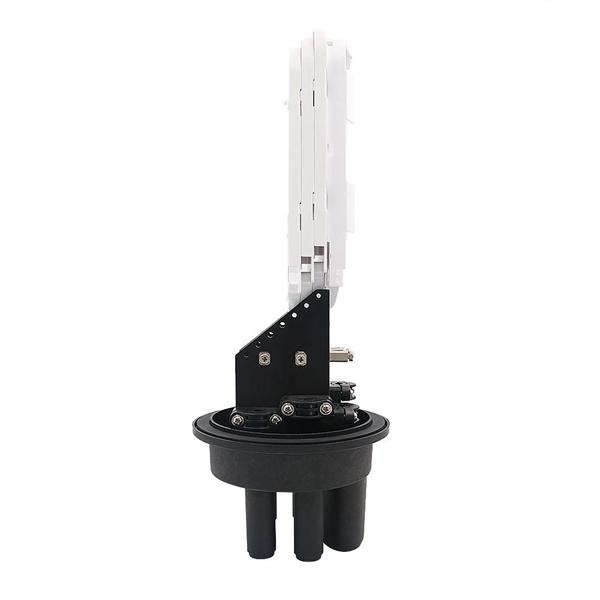
A typical fiber optic splice enclosure consists of several key components that work together to protect and organize the fiber splices. Standard enclosures contain: 1) Housing, 2) Cable fixation clamps, 3) Splice trays, 4) Sealing system. A splice box (also known as splice distributor) is a housing in which fiber optic cables begin or end. Fiber optics are fanned out in splice boxes that are situated at the end of fiber optic transmission paths. Optical cable joint box The optical cable joint box permanently connects two optical cables together and has a joint part for protecting components. The optical cable connection part, that is, the optical cable joint, is the part where the. An optical cable split fiber box, also known as a fiber distribution box or fiber optic splice closure, is a device used to terminate, splice, and distribute optical fibers. In this response, we will focus on the. This guide optimizes the original text by delving deeper into the three pillars of fiber network longevity: the impact of splicing technology, the strategic selection of splice boxes, and the essential maintenance protocols needed to ensure sustained, high-speed functionality. Fibre optic cables are manufactured in standardized lengths –.
[PDF]

Different networks have different needs when it comes to fiber optic joint closures. At Multilink, we have a variety of closures to meet these needs, including inline types and drop terminals. In our selection, you can find the following termination. Different networks have different needs when it comes to fiber optic joint closures. At Multilink, we have a variety of closures to meet these needs, including inline types and drop terminals. In our selection, you can find the following termination enclosures and splice boxes for use with different cable sizes and numbers of drops: Optima™: The Op. The securing, storing and supporting of fiber optics and splices makes up an important step of fiber optic deployments in the field. Whether connecting to aerial or underground cables, telecommunications companies rely on fiber optic closures to protect and facilitate fiber splices and regular maintenance in Fiber to the Home (FFTH) and other indoo. With more than 35 years of experience, Multilink is a leader in the telecommunications industry. We make innovative products and help our customers succeed by providing high-quality equipment that's laboratory tested and proven to perform. Telecommunications companies often have unique requirements for their equipment. If you have a specific fiber.
[PDF]

The typical specification range of return loss of a fiber connector is -15 dB to -60 dB. Return loss is also known as reflection loss. It indicates the amount of signal reflected back to the transmitting end. Return loss refers to the power loss caused by the reflection of part of the signal back to the signal source during transmission due to the discontinuity of the transmission. Insertion loss, also known as attenuation, is the loss of optical power that occurs when light passes through a fiber optic connector. It is caused by factors such as misalignment, air gaps, and imperfections in the connector components. The lower the insertion loss, the better the performance of. Reflectance (which has also been called "back reflection" or optical return loss) of a connection is the amount of light that is reflected back up the fiber toward the source by light reflections off the interface of the polished end surface of the mated connectors and air. It is also called. Insertion Loss (IL) is the amount of optical power lost as the signal travels from one point to another in a fiber optic link, usually across connectors or splices. Formula for. In optical fiber communication, insertion loss and return loss are two important parameters to evaluate the quality of interfaces between some optical fiber components, such as optical fiber connector, fiber patch cable, pigtail fiber, etc. While it's natural to have.
[PDF]

The max insertion loss of a fiber patch cable is 0. 75 dB (the maximum acceptable value) in the TIA standard. Insertion loss (IL) and return loss (RL) are key performance indicators of fiber optic patch cords. This article explains their concepts, standards, testing methods, and FiberMania's quality assurance workflow to ensure optimal network performance. Fiber optic patch cords are crucial components in. A: Fiber optic loss refers to the reduction in signal strength as it travels through the fiber optic cable. This can be due to various factors, including attenuation, connectors, and splices. Q: How is fiber optic loss measured? A: Fiber optic loss is typically measured using an Optical Loss Test. The estimate, called a "loss budget" is calculated using typical component losses for each part of the cable plant - the fiber, splices and/or connectors. If the measured loss exceed the calculated loss by a significant amount (remembering the inherent uncertainty in all measurements), the system. Insertion loss is usually shortened to IL, and the unit of measurement for insertion loss is dBm. ) in transmission systems. It is the power attenuation of the signal after. At TARLUZ, we specialize in manufacturing high-performance fiber optic patch cords that comply with global industry standards, ensuring optimal signal integrity and long-term stability.
[PDF]
For most commercial projects, expect to pay $50–$150 per fusion splice point - but that number can swing in either direction based on the factors below. The "per splice" rate is the most common pricing unit contractors quote for fiber work. Fiber optic splicing costs vary widely depending on project size, location, fiber type, and site conditions. This guide lays out cost expectations, with clear low–average–high estimates and regional nuances. Includes fusion/splice, testing, and basic materials. Understanding these factors can help businesses and individuals budget effectively for fiber optic. I usually bill T&M, but it works out to about $175-250 for setup/teardown per site and $4-7 per fiber for prep in a new tray in an existing case and splicing depending on if it's flooded or dry cable. Add another $50-75 to prep a new case endspan or $100-150 for a new case midspan with overcut on. Fiber-optic cable materials typically cost $1 to $6 per linear foot, depending on fiber count and cable type. Commercial building installations with 100-200 network drops generally range from $15,000 to $30,000. Single-mode fiber costs less per foot than multimode fiber, but it requires more. The price of fiber optic cabling depends on cable type, length, installation method, and surrounding materials. Typical costs hinge on fiber count, indoor versus outdoor use, and whether trenching, splicing, or termination is required.
[PDF]

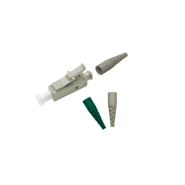
The connectors used in cold splicing typically consist of two parts: a ferrule and a body. The ferrule is a small, cylindrical piece that is designed to hold the fiber in place and maintain its alignment with the other fiber. Optical fiber cold splice technology is based on the use of mechanical connectors to join two fiber-optic cables. Get the wrong connector type, the wrong polish, or skip proper fusion splicing technique—and you're looking at elevated signal loss, increased back reflection, and a. Fiber optic joints or terminations are made two ways: 1) splices which create a permanent joint between the two fibers or 2) connectors that mate two fibers to create a temporary joint and/or connect the fiber to a piece of network gear. This is essential for extending network reach, repairing breaks, or connecting cables in data centers and telecom infrastructure. The goal is to align the microscopic glass cores (typically. In this guide, we cover the basics of fiber optic splicing, how to perform splicing using two different methods, and finally some best practices to perform good fiber splicing. What is Fiber Optic Splicing and Why is it Needed? – #1.
[PDF]

In this guide, we'll walk you through exactly how to splice fiber without a fusion splicer, covering the tools you need, the step-by-step process, performance specs, and common mistakes to avoid. By the end, you'll be equipped to make clean, low-loss connections in any field scenario. What is a. Infield installations, splicing is a faster and more efficient method and is used to restore fiber optic cables when a buried cable is accidentally severed. There are 2 methods of splicing, mechanical or fusion. Both methods provide much lower insertion loss compared to fiber connectors. Experts who add quality contributions will have a chance to be featured. Instead, it uses a small plastic or metal device to hold the fiber ends tightly together. A special index-matching gel is often used inside the splice to help light pass through the connection. The pre-terminated fiber optical cable is produced in the factory. The connector is made and well test. Simply plug and play. However, the length is fixed with a pre-made fiber optical cable. You can't get all the length you need. In this video, you will see how to use the LC coupler to join two. This blog post looks at the various options available to installers for responding to these issues; from splicing and field-fit connectors to factory-terminated or pre-connectorization. Splicing in the Field When fiber was first deployed, it was mechanically spliced, meaning that fibers were.
[PDF]

You can't directly connect a fiber optic cable to your router. You need an intermediary device. The key component is an Optical Network Terminal (ONT) or Optical Network Unit (ONU). Why Use Fiber Optic Internet? Before diving into the setup, let's quickly recap why fiber optics are worth the effort: Lightning-fast speeds (up to 1 Gbps or higher). Low latency for. The process to connect fiber optic cable to router requires careful attention to detail, but I'll walk you through every critical step with the precision and clarity you deserve. This comprehensive guide combines industry standards with field-tested practices to ensure you achieve a rock-solid. The fiber optic cable does not plug directly into a standard home router because the signal type must be translated. Our Experts are helping user's, who are facing issues with their tech gadgets like Router, Modem and extender. Here's a step-by-step guide to help you through it. Understand the Basics Before diving in, familiarize yourself with the components involved:. Connecting a fiber optic cable to a router involves a few key steps and specialized equipment. Check Your Fiber Optic Equipment Before you start, make sure you have the necessary equipment: Fiber Optic Modem (ONT – Optical Network Terminal):.
[PDF]

A8: Yes, multimode fiber optic cable can support high-speed data transmission depending on the fiber type and network equipment used. Multimode fiber (MMF) is an optical fiber designed to carry multiple light propagation paths—or modes—simultaneously. This is made possible by its relatively large core diameter, typically 50 or 62. 5 microns, compared to the ~9-micron core in single-mode fiber. The wider core accepts light from. Multi-mode optical fiber is a type of optical fiber mostly used for communication over short distances, such as within a building or on a campus. Multi-mode links can be used for data rates up to 800 Gbit/s. Multi-mode fiber has a fairly large core diameter that enables multiple light modes to be. In the realm of telecommunications and networking, multimode fiber optic cable plays a crucial role in efficiently transmitting data over short to medium distances. This guide aims to provide a concise understanding of multimode fiber optic cable and its applications. These fiber cables are structurally designed to transmit several light signals simultaneously, each of which is directed. Unlike copper cables, which rely on electrical signals, fiber optics use pulses of light to transmit data—offering unmatched bandwidth, low interference, and long-distance capabilities. But not all fiber cables are created equal: multimode (MM) and single mode (SM) fibers are the two primary types.
[PDF]
Configurations of 1x1 to n x m (e., 1x8 or 2x2) are available. The insertion loss of MM switches typically amounts to approximately 0. These switches can be delivered with any of the. Multimode fiber optic switches have emerged as a crucial component, enabling seamless connectivity and efficient data transmission. The MCSW Series Multicast Fiber Optical Switches enable simultaneous connection of one input to all outputs without loss. They support fully non-blocking, conflict-free switching of any number of optical inputs to any outputs, with complete configuration flexibility. The system is entirely passive. The Siemens Scalance X204-2 Multimode Switch requires a 24V UL Listed for Fire Application, Power Limited - Regulated Power Supply. Its Input Voltage is Regulated 24VDC and its Input Current is 265mA @ 24VDC. It is powered from the battery backed up local 24V power supply. Was this helpful? Does. For extremely precise measurement systems and sensor applications as well as for telecommunication applications LASER COMPONENTS offers fiber optical multimode (MM) switches with a fiber core diameter of 50 µm to 600 µm. There are switches are for all different kinds of requirements. Configurations. CONFIGURING THE SWITCH IN DESIGO CC/CERBERUS DMS. CYBERSECURITY DISCLAIMER.
[PDF]
In conclusion, choosing the right fiber optic connectors is an important decision that can have a significant impact on the performance and reliability of your fiber optic network. By considering the various factors.
[PDF]

Plug an SEL-2810 Fiber-Optic Transceiver With IRIG-B directly into a standard 9-pin serial connector (DB-9). No special mounting is required. The SEL-2810 receives power from the host device via the connector; no separate power supply or power wiring is needed. It also requires no. Improve safety, signal integrity, and reliability by using optical fiber instead of wire for instrumentation, protection, automation and other applications that benefit from economical fiber-optic links up to ½ kilometer long. Fiber-Optic Link— Establish EIA-232 communication between devices over a. The RLH Contact Closure Fiber optic converter transmits 8 digital input signals over fiber optic cable. Applications include alarm event triggering, building automation, environmental control systems, fire & alarm systems, gate control, traffic signal control equipment, and more. Use two optical fibers instead of 32 wires between outdoor or remote equipment and the control building to reduce costs, improve safety, and boost reliability. SFP transceivers bridge electrical and optical signals, making them indispensable in data centers, telecom networks, and.
[PDF]

Over time, the constant expansion and contraction can make these cables brittle, increasing the risk of breakage, especially at joints and connectors. Ice accumulation is another significant concern in freezing weather. Fiber optic cables are the backbone of modern high-speed data transmission, offering unparalleled speed and reliability compared to traditional copper wires. Many advantages come with installing fiber optic cables over traditional copper cables, but that doesn't mean they are invincible. Fiber optic cabling problems with extreme cold happen when water finds its way into the ducts housing the cables. If water has the chance to enter into. Cold weather can affect fiber optic cables, but they are generally more resilient to temperature extremes compared to other types of cables, such as copper. Here's how cold weather can. For example, Bulgin's 4000 Series Fiber connector is the smallest sealed standard interface connector on the market. The fiber connection is UV resistant, salt spray resistant and sealed to IP66, IP68 and IP69K, while still providing an industry-standard LC interface as specified by IEC 61754-20. It's also widely utilized in telecommunications services, including the internet, television, and cellphones. Fiber optic internet connections are more popular globally because they provide various benefits over regular.
[PDF]
