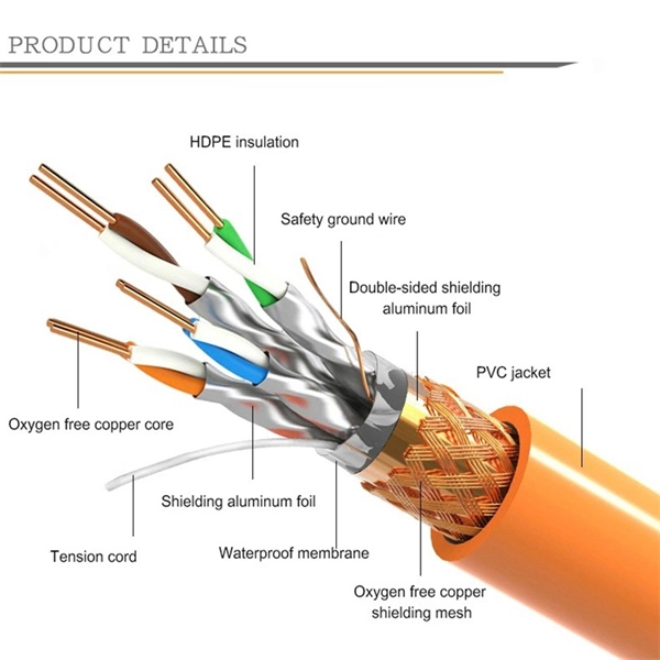
They support link aggregation protocols such as Link Aggregation Control Protocol (LACP) and Static Link Aggregation, which allow multiple physical links to be combined into a single logical connection. This enhances bandwidth, redundancy, and ensures failover capability in case of a. The three layers of a traditional three-layer network design are the core layer, aggregation layer, and access layer. Together, these layers can offer consumers a network that is safe, reliable, and affordable. As the physical part of the aggregation layer, aggregation switches typically play a. An aggregate switch is a high-capacity network switch that consolidates connections from multiple access switches, acting as a central point for managing network traffic and providing enhanced bandwidth capabilities. It is essential for larger networks requiring efficient data flow. This article looks at what each such tool does, compares how they differ from each other, and offers suggestions as to what sort of network each. The aggregation (sometimes also called distribution) layer is a real crossroad. Its primary goal is to increase network scalability by providing a single place to interconnect multiple access switches and the core layer.
[PDF]
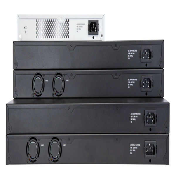
This article discusses such episodes, known as data center outages, looks at their causes, and shares best practices for preventing them. Malfunctioning Hardware 3. Environmental and Natural Disasters 6. Software Failure. 2025 revealed how data center outages, from fires and mechanical failures to hyperscale cloud region events, can cascade quickly in an AI-driven world, highlighting the growing importance of physical resilience, control-plane reliability, and clean recovery. Physical infrastructure failures, such. As hyperscale AI campuses expand and real-world attacks strike supporting systems, the gap between how data centers operate and how they're protected is becoming harder to ignore. AWS Outage: What Are the Lessons for Enterprises?. Fault-tolerant systems are systems that are engineered to detect failures, isolate faulty components, and recover quickly without significant impact on operations. This is achieved through a combination of physical, logical, and data redundancy, sophisticated fault detection mechanisms, and. Data center failures can be caused by a variety of factors, some of which are common and impact most people (such as human error), while others are rare. Whether it is rare or not, the impact is usually the same: lost productivity, poor service that affects customers or staff, and costs more. Introduction to Fault Detection through BMS 2. Fault Detection & Diagnostics (FDD): Component Breakdown 5. Predictive &.
[PDF]
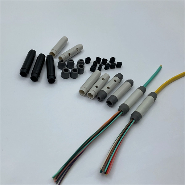
In the rapidly evolving landscape of modern networks, fiber optic connectors play a pivotal role in ensuring seamless data transmission and connectivity. These essential components bridge fibers, enabling the efficient transfer of information across various applications and. Among these components, fiber connector types are essential to network performance, reliability, and scalability. This guide will walk you through the most common fiber connector types, explaining their characteristics, advantages, and typical use cases. The connector body, which is the protective housing that holds and protects the ferrule, plays a key role in ensuring a robust and durable connection. Fiber optic connectors can. Whether it's for internet networks, telecommunications, or data centers, fiber optic cables rely heavily on connectors to establish secure and efficient connections. They link fiber optic cables, allowing data to move quickly with minimal loss. In this guide, you'll explore various types of fiber optic cable connectors, each with unique features and. Learn about the top 4 fiber optic connectors (LC, SC, ST, MTP/MPO) and find the best options for your network, optimizing performance, reliability, and data transfer in a technological age.
[PDF]
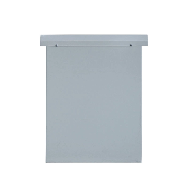
Attach a ground wire from one of the threaded studs (A) at the bottom of the housing, to the mounting plate (B). The ground resistance between all system parts shall be < 0. Power from factory ground must be installed by a qualified electrician. Each DISTRIBUTION BOX and controller must be grounded. On the US market, a 5. This position is the connection point of the grounding wire in the. Today, we're diving deep into the world of distribution box grounding, breaking down the standards, and shining a light on those sneaky mistakes that even experienced electricians sometimes make. Whether you're a seasoned pro or just starting out, this comprehensive guide will give you practical. How to make proper & safe electrical ground wiring connections in the box: This article describes options for connecting a metal electrical box to the grounding conductor & connecting the grounding conductor to a fixture such as a ceiling light or ceiling fan. It ensures stability and provides a critical path for fault current, preventing severe shocks and fire hazards. This guide covers the essential principles and procedures for grounding an electrical panel per the National. To safely ground a metal box, connect an equipment grounding conductor (typically a bare or green insulated wire) from the box to the main electrical panel's ground bus bar. Use a green grounding screw to secure the wire to a designated threaded hole in the metal box itself. This critical step.
[PDF]
This paper analyzes the basic principle and function of relay protection, summarizes the common fault types, and analyzes the fault analysis methods and treatment measures combined with actual cases. A method of fault tracking for relay protection devices is presented in this paper. Fault tracking means that after the failure of relay protection devices, the anomalies and warning informa-tion are obtained through data-mining technology, and then, the fault tracking algorithm is used. Relay fault diagnosis refers to the process of identifying and analyzing faults or abnormalities in protective relays. However, in actual operation, the relay protection device may cause failure due to hardware failure, software problems or external. For a long time, the fault diagnosis technology of relay protection consists of isolated cases and does not have a systematic method.
[PDF]
Attach a ground wire from one of the threaded studs (A) at the bottom of the housing, to the mounting plate (B). The ground resistance between all system parts shall be <. The protective grounding system, which includes conductor grounds and worker bonding, must be engineered to protect workers from hazardous voltages that can be created by line reenergizing, lightning, or induced oltage. If more than one crew is working independently on the same deenergized line or. Power from factory ground must be installed by a qualified electrician. Each DISTRIBUTION BOX and controller must be grounded. On the US market, a 5. 26 mm 2 (10 AWG) ground wire must be used, and in all other markets a 6 mm 2 must be used. The neutral conductor is typically the grounded conductor connected to the system's neutral point, carrying current under normal operation. Grounding electrode conductors must be connected at. The correct connection method of Distribution box grounding wire mainly includes the following steps: 1. Whether you're a seasoned pro or just starting out, this comprehensive guide will give you practical. This technical article covers protective grounding requirements for steel tower and wood pole supported transmission and distribution lines, and insulated power cables. Protective grounds must be installed so all phases of lines or cable are visibly and effectively bonded together in a multi-phase.
[PDF]
