If you encounter any of these issues, check the optical connector for damage or dirt, inspect the fiber optic patch cord, ensure the optical module is correctly installed, and check the device settings for compatibility. Subsequently, the driver semiconductor laser (LD) or light-emitting diode (LED) emits modulated optical signals at the corresponding rate. After transmission through the optical fiber, the receiving interface converts the optical signals into electrical signals using a photodetector diode and. An optical module is a typically hot-pluggable optical transceiver used in high-bandwidth data communications applications. Optical modules typically have an electrical interface on the side that connects to the inside of the system and an optical interface on the side that connects to the outside. The Transmitter Optical Sub Assembly (TOSA) is responsible for the emission of light. Its primary function entails converting electrical signals into optical signals.
[PDF]
Customize MOQ of Fiber Optic Modules manufacturer from Laos, deal with top Fiber Optic Modules verified suppliers. Our products and services cover optical design, optical components manufacturing, lens assembling, optical measurement, Laser Diode modules, and Fiber Collimator/Coupler. The 10 DAY LENS SAMPLING service we offer is the fastest speed in the market. Our goal is to provide customers with a one-stop. Product Specifications/Features SFP Optical Transceivers are hot-swappable, compact media connectors that provide instant fiber connectivity for your networking gear. They are a cost effective way. The optical transceiver is designed for use in 100/155Mbit/s data links. It provides the SC. QSFP-40G-LR4 40g QSFP 1310m 10KM Fiber-optic modules TAKFLY COMMUNICATIONS CO. TAKFLY COMMUNICATIONS CO. Dive into our online wholesale fiber-optic modules products catalog on globalsources. com! Source over 605 fiber-optic. CFP 40GBASE-FR optical transceiver module. D9901 DCM Gateway Card - Optical: 6 ports. Optical Protection Switching Module REMANUFACTURED. Market Forecast By ProductCategory (Cable Assemblies, Connectors, Optical Transceivers, Free Space Optics, Fiber, and Waveguides, Silicon Photonics, PIC-based Interconnects, Optical Engines), By Application (Data Communication, Telecommunication), By Interconnect Level (Metro and Long-haul Optical.
[PDF]
Remove the module from the receiver frame. Use the Allen wrench to remove the module cap screws located at the top, middle and bottom of the module (Figure B). For 37 and 16/16 position use a Phillips screw driver to remove the (2) 2-56 screws. Terminating fiber optic cables essentially means putting connectors on fiber optic cable so that you can connect the cable to various devices or network components. Think of it as the equivalent of connecting the dots in a complex puzzle; without proper termination, the whole system can break down. How to remove/disconnect fibre cable from Telus modem? Pull the green thing from the metal thing If you pull it out make sure to put the fiber connection in a plastic bag or blow it with air before plugging it back in, Fiber laser modules and a single spec of dust/lint/crumb can affect your speeds. Terminating fiber optic cable is a crucial step in the installation process, as it ensures a reliable and efficient connection. The contact can only be installed from one side. Ensure that the contact is squared up with the corresponding module location. Once in place, pull the wire. The transceivers for the router are hot-removable and hot-insertable field-replaceable units (FRUs). After you remove a transceiver or when you change the media-type configuration, wait for 6. IN THIS VIDEO I WILL SHOW YOU How to Disconnect Optical Fiber Cables from the Connector #DISCONNECTOPTICALFIBER.
[PDF]
Essentially, an OXC is a device that allows for the interconnection of multiple optical fibers, facilitating the routing of optical signals from any input fiber to any output fiber. This functionality is crucial for managing the vast amounts of data transmitted through optical. An optical cross-connect (OXC) is a network device that switches high‐speed optical signals between fiber inputs and outputs without converting them to electronics. In the 1980s, when transmission speeds supported by optical fibers increased from 45 Mbit/s to 2. 5 Gbit/s, carrier networks. The Optical Transport Network has emerged as a dominant standard to address these needs, offering robust transmission, multiplexing, switching, and management capabilities for optical signals. Compared with traditional ROADM based on separate boards and inter-board fiber patch cords, OXC uses integrated interconnections to build an all-optical switching resource pool, achieving highly integrated, fiber. Optical Cross-Connects (OXCs) are critical components in modern optical networks, enabling the switching of optical signals between different paths without the need for electrical conversion. This technology supports scalability, flexibility, and high performance for backbone networks, data‑center interconnects, and next-generation mobile.
[PDF]
Run the display device command to check the switch model. Log in to com/onlinetoolsweb/lpcmmt/en/index. html to view the optical module types supported by the switch. If you know the model or type of an optical module, you can view the section "Pluggable Modules for Interfaces" in the Hardware Description to look up parameters of the optical module, including the center wavelength, transmission distance, fiber types supported, receive optical power, and transmit. Taking the Huawei 5700 series switches as an example, the commands to view optical module information are as follows: Transceiver Type :1000_BASE_SX_SFP Connector Type :LC Wavelength(nm) :850 Transfer Distance(m) :300(50um),150(62. 5um) Digital Diagnostic Monitoring :YES Vendor Name. The following uses the Moduletek SFP-10G-LR module connected to a Huawei S6700 switch as an example to introduce how to read information of the connected optical module on a Huawei switch. Run the display transceiver [interface interface-type interface-number | slot slot-id] , to view the information on. Here are the common commands to use to display hardware-related information on Huawei Routers. The inventory information such as serial number, product code,optical module,device, power,voltage,temperature,fan, CPU and memory are very important on operation and troubleshooting purposes. The specific viewing information is as follows:.
[PDF]
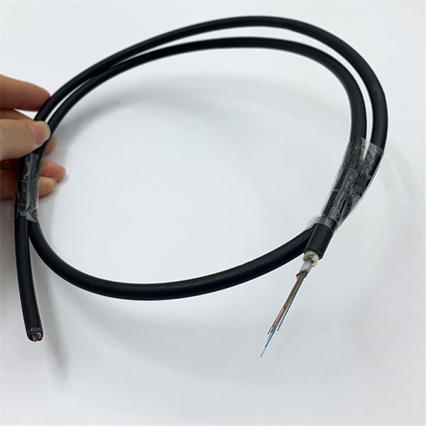
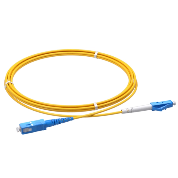
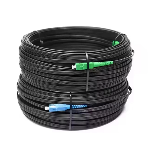
The single-fiber optical module has only one optical fiber port, and only one optical fiber can be inserted to transmit and receive optical signals at the same time. One fiber is required for. Single fiber modules (BiDi) use one fiber for both transmitting and receiving data. This saves space and money. Dual fiber modules use two fibers. They are easier to set up and give steady communication. It uses WDM technology to realize the bidirectional transmission of optical signals on one optical fiber. BIDI module only has 1 port, wave filtering through the filter of module, and finished the transmitting of 1310nm optical signal. Appearance and use: single fiber optical module has one optical fiber interface, which connects one optical fiber; dual-fiber optical module has two optical fiber interfaces, which connect two optical fibers; 2.
[PDF]

Built with GF's advanced silicon photonics technology, the SCALE CPO solution utilizes both coarse and dense wavelength-division multiplexing (CWDM, DWDM) for bi-directional data transmission over each optical fiber for significant improvements in bandwidth density and system. Built with GF's advanced silicon photonics technology, the SCALE CPO solution utilizes both coarse and dense wavelength-division multiplexing (CWDM, DWDM) for bi-directional data transmission over each optical fiber for significant improvements in bandwidth density and system. MALTA, N., May 04, 2026 (GLOBE NEWSWIRE) -- GlobalFoundries (Nasdaq: GFS) (GF) today announced the introduction of its SCALE™ optical module solution for co-packaged optics (CPO). GF's SCALE solution, or Silicon photonics Co-packaged Advanced Light Engine solution, is the industry's first Optical. MALTA, N. 9, 2024: IBM (NYSE: IBM) has unveiled breakthrough research in optics. These pressures are driving renewed momentum behind co-packaged optics (CPO). According to LightCounting, sales of lasers and photonic integrated circuits for optical transceivers are expected to grow from $2. 9B by 2029, fueled largely by AI data centers.
[PDF]

A constant trend in optical modules is to offer higher data rates within the size-limited and thermally-limited form factor by using smaller, integrated Power and Data-Converter solutions. The SFP module is a hot-pluggable optical transceiver used for connecting network switches. It converts electrical signals to optical signals and vice versa. For the 1G SFP module, it is primarily divided into the following two categories: Optical SFP Transceiver Optical transceiver connection RJ45. The optical module serves as a crucial component in optical fiber communication systems, operating at the physical layer, which is the lowest layer in the OSI model. An. Optical modules and media converters are both key photoelectric conversion devices widely used in fiber optic communication, data centers, enterprise networks, and broadband access systems. Many users are confused about their roles, differences, and connection rules. This article will clarify. Microwave photonics technology (MWP), which has been applied to various radar, Telcom, Electronic Warfare systems, is now facing more and more challenging development trend of miniaturization and modular array for increasing node counts and system complexity.
[PDF]
Lighting Control System | Smart Lighting Wiring Setup | Full Guide In this video, you will learn how to connect and install a Lighting Control System step-by-step. This guide covers wiring setup, switch modules, dimming control, sensor setup and panel . as a guide for proper and reliable installation. The mounting location should e selected and prepared based on the application. All electrical wiring and mounting hardware (i. ) should be prepared with consideration of the requirements o cuit breaker before. Intelligent Lighting Controls' installation guides provide detailed instructions on how to install all of our solutions. The Lightolier Controls Optio Lighting Control Panels are high-performance, wall mounted lighting control panels which offer a wide range of dimming and relay modules to accommodate any lighting control application.
[PDF]

First, inspect the optical module appearance for physical damage, cracks, missing components, poor solder joints, or burn marks. Next, compare voltage, resistance, and waveform parameters between a normal it and the suspected faulty one, both in powered and unpowered states. As core components of optical communication systems, the proper installation and use of optical modules directly impacts network stability. This article systematically identifies common anomalies during optical module installation. However, during installation and daily operation, various issues may arise. The following will introduce the causes of various problems and how to deal with them. Optical module method/step 1. During the test, the value of the module I BiasADC is 0, and the TXLOP-ADC and. These compact devices convert electrical signals to optical signals and vice versa, enabling data transmission over fiber optic cables. While generally reliable, failures do occur, leading to frustrating downtime, performance degradation, and costly troubleshooting. This comprehensive guide details. Have you ever dealt with sudden network drops from faulty optical modules? Issues like this cannot only break communications, but they can really jeopardize business continuity.
[PDF]
As an essential component of optical fiber communication, optical modules are optoelectronic devices that facilitate the conversion between optical and electrical signals during the transmission process. Operating at the physical layer of the OSI model, optical modules are core devices in optical. That is, metal medium communication represented by coaxial cables and network cables is gradually being replaced by optical fiber media. Optical modules are a core component of optical fiber communication systems. They are used in fiber optic communication systems to transmit data over long distances with minimal loss and interference. These modules typically consist of a laser or LED transmitter, a. An optical module is a typically hot-pluggable optical transceiver used in high-bandwidth data communications applications. As the core optoelectronic devices operating at the Physical Layer of the OSI model, their.
[PDF]

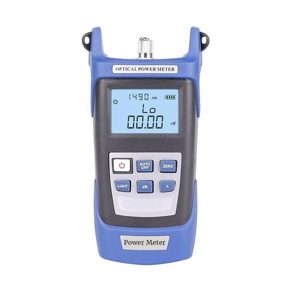
This quick-reference guide focuses on what to measure, how to interpret results, and what to do when findings indicate marginal performance. Whether you're a network engineer validating new inventory or an integrator preparing for deployment, knowing how to test optical transceiver modules can save time, reduce failures, and ensure SLA compliance. Unchecked optical modules can cause: Testing ensures compliance with IEEE 802. 3 and MSA. This article provides a comprehensive guide on measuring key performance indicators to evaluate the functionality of optical modules, with a specific focus on the sfp28 transceivers. A comprehensive understanding of the working principle of an optical module is essential for determining the. Evaluating the performance of optical modules is a practical discipline: you must verify optical power and signal quality, confirm electrical/optical compliance, validate link-level behavior under real traffic, and document results in a way that supports reliability engineering. This. The optical module serves as a crucial component in optical fiber communication systems, operating at the physical layer, which is the lowest layer in the OSI model. Its primary function is to achieve optoelectronic conversion by converting electrical signals into optical signals and vice versa.
[PDF]
Segmented dimming is a feature of the Magic Leap 2 that applies a darkening tint behind specific digital content. Similar to a drop-shadow, this dimming improves the visual quality of a digital object by making it appear brighter or more opaque. The dimmer uses a lower resolution panel and therefore, developers must be conscious of it's use and is best used for larger objects. As of the February 2023 release, all virtual. The main scene of this project displays two cubes, one cyan and one red. The Segmented Dimmer material opacity will adjust based on the MLCamera stream value calculations. Think of this as a tint applied to the background under all the virtual content, in which you can control its opacity value. A Segmented Dimmer, which allows applications to locally. Th is function is commonly referred to as dimming control. Th is article describes some basic LED theory and several techniques used to provide dimming control to switched-mode LED drivers. Th e concept of the brightness of visible light from an LED is fairly easy to understand. Assigning a. It the utility model is related to LED light source room lighting field, more particularly to a kind of segmented LED dimming control circuit, a kind of segmented LED dimming control circuit, the light-source brightness of LED lamp is automatically adjusted to realize by the collective effect of.
[PDF]
00 Original price was: $285. Add an LC fiber optic connection to your Blackmagic Studio Camera, Teranex Converter, ATEM hardware, or any other professional device that supports SFP cages with. Help others learn more about this product by uploading a video! Looking for specific info? Would you like to tell us about a lower price? Found a lower price? Let us know. Although we can't match every price reported, we'll use your feedback to ensure that our prices remain competitive. 6G data rates support SD, HD, and 4K resolutions, and the fiber optic communication allows. FiberMall SFP+ Transceivers are hot swapping, cost effective modules supporting data rate of 6Gbps/8Gbps/10Gbps/16Gbps/32Gbps and up to 120km transmission. Learn more Spread the cost of your purchases over 3 to 24 months with an interest rate from 0. There's no fees if you pay on time. All set! You can manage payments in the Klarna app or website Down payment may be required. Klarna Monthly.
[PDF]

This video shows real on-site footage of electrical installation, demonstrating safe and standardized wiring methods used by professionals. Whether you are setting up a new telephone line or troubleshooting an existing one, understanding the basics of wiring is essential. In this article, we will explore the key components of a telephone line box and the. In this video, we'll walk you through the process of wiring a home distribution box with a detailed connection diagram. What is Distribution Board? Distribution board. mounted in OnQ Service Center Enclosures and come in several different telecom/video combinations; an example (6+8) is shown yle fittings for connecting incoming and outgoing cables. ve an 8 position 110 punch-down connector for incoming 4 ine service and 110 (8) position punch-down connectors. With the right wiring diagram, you can easily complete the job and get your outside phone box up and running in no time. If you're looking for a wiring diagram to help you install an outside phone box, then you've come to the right place. From there, the wiring is divided into separate lines for different areas of the house, such as bedrooms, living rooms, and kitchens. Each line is then connected to a.
[PDF]