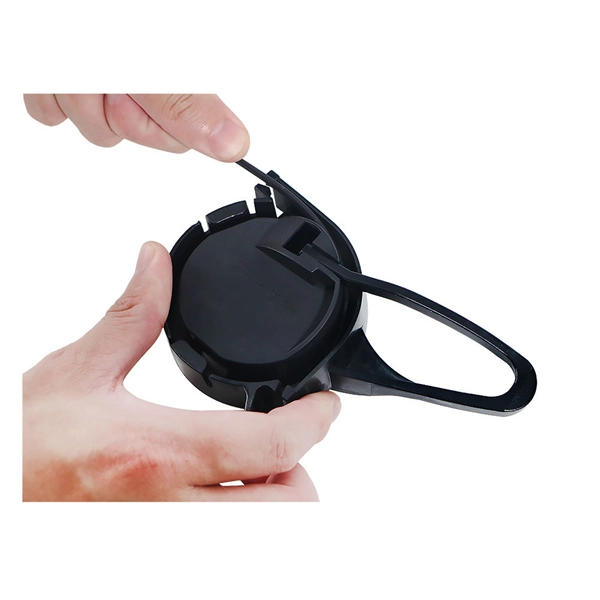
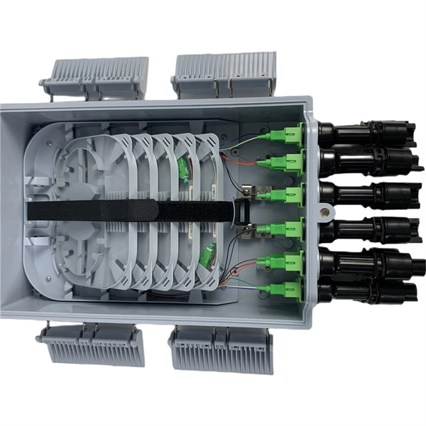
Learn how to install a fiber optic termination box step-by-step for FTTH projects. Covers mounting, splicing, routing, labeling, and testing for indoor/outdoor use. Installing a fiber optic termination box is one of those jobs that looks simple on paper, but it's easy to do poorly in the field. A. A fiber termination box is the standard instrument used in fiber optic networks to connect, secure, and protect optical fibers at the terminating point. It functions as a junction between the incoming fiber cable and the outgoing customer-side fiber cable, where one fiber can be spliced, patched. FTTP or fiber To The Premises applications have reinforced the importance of reliable and stable fiber optic terminations. They also feature resistance to moisture, impact, chemical exposure. A common question we receive is: How do you use a fiber-optic termination box? We recommend using a termination box if you're ordering an assembly with more than two strands. It helps keep your connectors free from contamination and dust, while also keeping your assembly neat and organized. It serves as a termination point for optical fibers, providing a secure and organized space for connecting and managing fiber optic cables. The following steps provide a detailed installation guide for fiber termination boxes: Before starting the installation, you will need the.
[PDF]
In conclusion, choosing the right fiber optic connectors is an important decision that can have a significant impact on the performance and reliability of your fiber optic network. By considering the various factors.
[PDF]
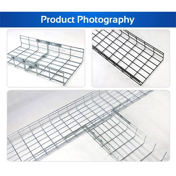
Optical cable tray is a system designed to protect and route fiber optic patch cords, cable assemblies to and from network cabinets, ODF and other terminal devices. Ducting offers ideal solutions for optical raceway requirements and application with pleasing appearance and easy. Our Fiber Cable Tray System is a comprehensive raceway solution for data center, enterprise, central office, and mobile switching center applications. Designed to route and protect fiber optic and high-performance copper cabling to and from network cabinets, distribution frames, and other terminal. Cable trays are a foundational part of this infrastructure, offering a secure, scalable, and organized method of managing fiber routing across diverse environments.
[PDF]

Recommendation ITU-T L. 12 specifies splices of single-mode and multimode optical fibres. It describes suitable procedures for splicing that should be carefully followed in order to obtain reliable splices between single optical fibres or ribbons. Typical applications of these methods include aerial, buried, and underground splices. (2) American National Standard Institute/National Fire Protection Association (ANSI/NFPA) 70, 1993. § 1755. 370 - RUS specification for seven wire galvanized steel strand. 400 - RUS standard for. ation or liability to users of this publication. Existence of a standard shall not preclude any member or nonmember of NECA or FOA from specifying or using alternate construc Code (NEC) in effect at the time of publication. Because they are quality standards, NEIS® may in some instanc s go beyond. RUS standard for splicing copper and fiber optic cables. (FOA) was founded in 1995 to help develop the workforce to build the fiber optic networks to support a rapid expansion in communications and the Internet. The charter of the FOA was to promote professionalism in fiber optics through education, certification, and.
[PDF]
stands at the forefront of innovation with its pioneering tunable fiber Bragg grating technology. Our unwavering dedication lies in crafting state-of-the-art tunable fiber optic devices and systems with diverse applications. We specialize in custom fabrication of fiber optical gratings (FBG) across wavelengths from 400 nm to 2000 nm, tailored to precise customer specifications. Using high-power laser irradiation, we permanently modify the refractive index of the fiber core, delivering FBGs with low optical loss and. Optical Gratings are optical components that consist of a periodic structure of parallel slits or grooves etched or ruled onto a substrate material. The leading manufacturers of Gratings are listed below. Narrow down on the list of companies based on their location and capabilities. Products include phase masks, fiber optics based sensor and system, partial discharge and twin grating cavity sensors. Gould Fiber Optics is estimated to have 50-99 employees. Our patented fiber. TECHNICA focuses on Fiber Bragg Gratings (FBG) based products. Implementing our Mission we deliver the highest quality, most reliable, and. Explore 16 top manufacturers and suppliers of Fiber Bragg Gratings in our comprehensive photonics buyers' guide. A fiber Bragg grating is a type of optical filter that is inscribed or "written" into the core of an optical fiber. It consists of a periodic modulation of the refractive index along the.
[PDF]

This practical file details experiments conducted in Optical Fiber Communication, covering modulation techniques, system components, and performance analysis. An optical fiber is a glass or plastic fiber designed to guide light along its length, widely used in fiber-optic communication, which permits transmission over longer distances and at higher data rates than other forms of communications. Fiber-optic communication is a method of transmitting. Availability of plastic optical fiber (POF) The plastic optical fiber used in some of these experiments is available for science distributors. It is a 1000micron (1mm) POF available from several suppliers. FOA has samples available at no cost for teachers at schools in the US. Key experiments include amplitude modulation, frequency modulation, and pulse width modulation, aimed at understanding fiber optic systems. This document summarizes 10 experiments on optical fiber communication: 1. Studying a 650mm fiber optic analog link and the relationship between input and received signals. Optical fiber communication Laboratory Optical fiber communication Laboratory List of Experiments: 1. To set up a analog optical fiber link 2. To measure the characteristics of LED and LASER 5. Tech curriculum designed to provide a comprehensive understanding of optical fiber communication systems. This lab offers an immersive, web-based simulator that enables you to explore and experiment with key concepts in optical.
[PDF]

Fiber splitters serve as essential components in optical networks. These devices divide an optical signal from a single input into multiple outputs. This process enables efficient signal distribution across various network points. Fiber splitters function without the need for external. In the intricate web of modern fiber optic networks, where data travels at the speed of light across continents, fiber optic splitters play a silent yet pivotal role. These unassuming devices enable a single optical signal to be divided into multiple paths, making them indispensable for sharing. A fiber splitter, also known as a beam splitter, is a passive optical device that splits an optical signal into multiple signals. By dividing a single optical signal into multiple signals, fiber. Fiber optic splitters are vital in modern communication networks. Fiber optic splitters, such as plcsplitter and fbt splitters, are crucial in maintaining signal integrity, with considerations for IL (Insertion Loss) and RL (Return Loss). They are integral components in the world of telecommunication and data networking, crucial to maintaining reliable and efficient communication infrastructures. There are two primary.
[PDF]
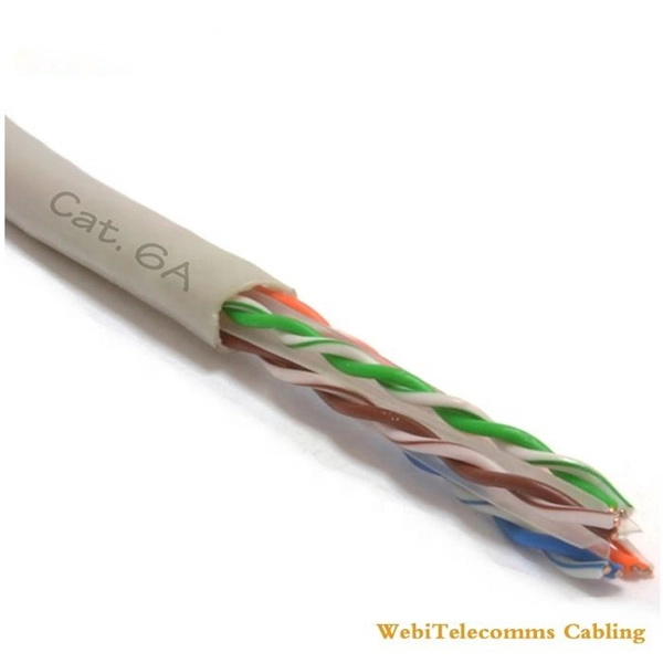
Fiber optic cable installation costs average $4,500 for most homeowners, with most installations ranging from $1,500 to $7,000. Computer repair costs depend on your project and location. Check with a local pro for your specific job. The installation type you choose and the layout of your. Homeowners and businesses typically pay for fiber optic cable installation based on distance, conduit needs, and labor. The main cost drivers include material type, run length, trenching or aerial work, and any required permits or inspections. This guide provides clear cost estimates, price ranges. Fiber optic cables consist of multiple fibers, each designed for high-speed data transmission. These fibers are thin strands, often as small as a human hair, that transmit data as pulses of light. Data aggregated from Q1 2026 contractor invoices across Texas, Ohio, and North Carolina.
[PDF]
We propose and demonstrate a fiber optic strain sensor based on a simple splice between a thin core fiber and a piece of conventional single-mode fiber. Mode dispersion generates an interference reflection s.
[PDF]
This is a list of terrestrial fibre optic cable projects in Africa. While submarine communications cables are used to connect countries and continents to the Internet, terrestrial fibre optic cables are used to extend this connectivity to landlocked countries or to urban centers within a country that has submarine cable access. In most of the world, a large number of such cables exist, often a. NotesThis list was initially developed as part of AfTerFibre, a project to map terrestrial fibre optic cable projects in Africa. • • • •.
[PDF]

In short length cables a visual fault locator (VFL) can find where the cut is or find the bad connector at patch panels. For longer distance cables, the use of an OTDR is required. Once the fault is located, fusion splicers and splice-on connectors can be used to complete the repair. Fiber optic cables are the backbone of modern networks, delivering fast and reliable data transmission. Accidental cuts, breaks, or other damage can disrupt your network and cause costly downtime. With the right tools and techniques, you can efficiently repair damaged fiber cables and restore. Fiber optics offers advantages like EMI immunity and low attenuation (0. 2 dB/km), but it's fragile—susceptible to breaks, bends, and contamination. Repairs focus on restoring the light path with minimal signal loss (<0. A fusion. Visual inspection and specialized tools like OTDRs, OPMs, and VFLs are essential for identifying and locating physical damage or faults in fiber optic cables. Emergency restoration planning involves implementing backup power solutions, network redundancy planning, and strategies for prompt. Fiber optic cables are critical components of modern communication networks, transmitting vast amounts of data at lightning speeds.
[PDF]
This guide provides a comprehensive engineering perspective on ODFs—beyond the basic “what is an ODF” explanation—covering structural design, fiber management, MPO/MTP integration, and selection criteria for modern high-density deployments. Why ODFs are the Foundation of. This complete guide explores everything you need to know about ODFs — from their structure, types, and key components, to installation best practices and modern design trends. Whether you're building a central office, data center, or FTTx distribution network, understanding the right ODF. In the complex architecture of fiber optic networks, the Optical Distribution Frame (ODF) serves as the linchpin for organizing, protecting, and distributing optical signals. As data centers, enterprises, telecom operators, and smart-building infrastructures deploy increasingly dense fiber links, ODFs provide the structured. An ODF is a central hub in fiber optic networks, crucial for managing and organizing the variety of fiber-optic cables and connections entering a facility such as a telco central office (CO). They provide efficient fiber optic management, connectivity, and protection. What is Optical Distribution Frame An Optical Distribution Frame (ODF) is the central hub of your fiber optic network.
[PDF]
The PL-1000D simultaneously monitors up to 16 fiber strands, eight on the OTDR and eight on the OSA, and operates standalone over dark fiber, lighted fiber, or a third party network without impacting network traffic. The device monitors the entire D. The PL-1000D simultaneously monitors up to 16 fiber strands, eight on the OTDR and eight on the OSA, and operates standalone over dark fiber, lighted fiber, or a third party network without impacting network traffic. The device monitors the entire DWDM C-band spectrum and provides the optical spectrum, OSNR, and OTDR measurements of the fiber. The OTDR locates fiber cut by sending high powered optical pulses into the fiber and creating Rayleigh back-reflections. The returning signals are measured and calculated, indicating the accurate location and intensity of the fault. The OTDR supports GIS (Geographic Information System) using Rest API, enabling precise geographic location of disrupt. The OSA enables the user to monitor the OSNR and optical spectrum of each fiber and shows a full, accurate and detailed picture of the wavelengths used in the fiber. OSADiagram Graphical Display of the OSA, from PacketLight's LightWatch NMS Please contact usfor a quote or further assistance.
[PDF]
To find the best routerfor fiber internet, we used our expertise to select items based on key specs, such as speeds, coverage, wireless standards, security, weight, and additional features. We've also delve.
[PDF]

The short answer is no - RJ45 connectors are designed for electrical Ethernet signals, while fiber optics transmit light pulses through glass or plastic. However, modern networks often combine both technologies. The fiber optic patch cable must, therefore, be carefully considered. Behind its slender appearance lies the fusion of core types, connector types, and polish levels, each chosen for a specific application. Choosing the right cable thus boils down to educating oneself about fiber optic patch cable. At ZION Communication, we design and manufacture a full range of fiber patch cords for: This guide will help you quickly understand the main types of fiber patch cords and how to choose the right solution for your project – and how ZION can support you with stable quality, flexible customization. To connect your fiber optic cable to a router, ensure you have the following: Fiber optic modem (ONT): Most fiber connections require an Optical Network Terminal (ONT), provided by your ISP. This guide outlines the key steps and considerations for effective cable management in fiber optic systems. Steps for Fiber Patching: Step 1: Identify the. When you build or upgrade a fiber network, the same four words pop up everywhere— fiber optic (bare fiber), pigtail, patch cord, optical cable. They're related, but they are not interchangeable. Mixing them up drives costs higher, increases loss, and slows your rollout. The good news? Once you nail.
[PDF]