Supported by air within insulated pillars, the busbar collects incoming electricity and conducts it for distribution to outgoing feeders. They are typically made from solid or hollow conductive metals, such as copper, aluminum, or brass. In electric power distribution, a busbar (also bus bar) is a metallic strip or bar, typically housed inside switchgear, panel boards, and busway enclosures for local high current power distribution, transmission, or switching substations. Its primary role is to carry large current loads and connect multiple circuits together. Think. A bus bar offers a low electrically resistant path to incoming or outgoing currents. Find out more about them in this article. What is a bus bar? An electrical bus bar is a solid-state conductor made from copper and aluminum- present in the industry for over 150 years. It carries higher amount of currents in a limited space and to which all the incoming and outgoing feeders are connected in a substation.
[PDF]
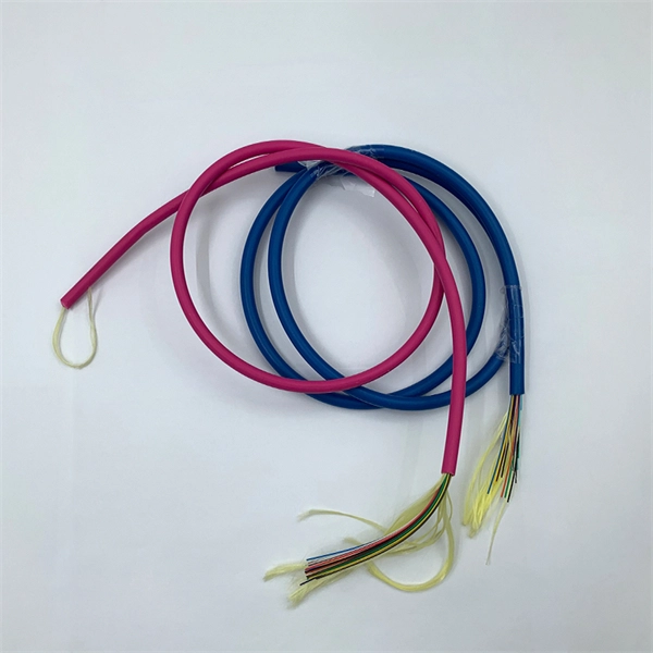
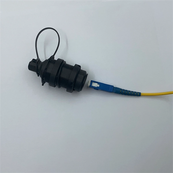
If you're new to fiber optics or want to enhance your technical skills, this guide will help you understand how to splice fiber pigtails safely and efficiently. --- 🔧 In This Video You'll Learn: ✅ What fiber pigtails are and why they're used ✅ How to strip, clean. The most efficient way to terminate a fiber run is by using a pigtail. A fiber pigtail is a short length of optical fiber that comes with a high-quality, factory-polished connector already installed on one end, leaving a length of exposed glass on the other. Instead of building a connector from. In this detailed video, we'll walk you through the fiber optic pigtail splicing process — from preparation to final testing. --- 🔧 In. Executive Summary: A fiber optic pigtail is one of the most commonly specified yet least understood components in structured cabling. Get the wrong connector type, the wrong polish, or skip proper fusion splicing technique—and you're looking at elevated signal loss, increased back reflection, and a. Break off the cable entry from the cover and from the back box. Tie the cable to the box and wrap the fibers around the center 2~3 times as shown.
[PDF]
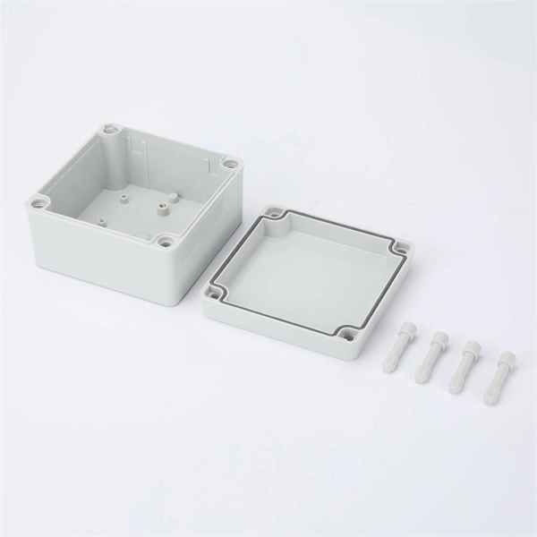
In this article, we will guide you through the step-by-step process of opening an electrical box safely and effectively. We will also highlight the necessary tools and materials you will need to complete the task. The electrical service panel, commonly known as the breaker box, acts as the central distribution hub for all electrical power entering a home. This metal enclosure receives high-voltage current from the utility company and safely divides it into various circuits that supply power to lights. So, before we dive into the discussion, here's a list of tools that you must have. Electric Drill/Screwdriver 2. Personal Protective Equipment Step 1. Clear your working area Step 2. Estimate the cover's weight Step 4. It is responsible for controlling and distributing the electrical current throughout your house, ensuring the safety and efficiency of your electrical appliances and devices. This article details the process of installing them, which helps you comprehend distribution boxes. An electrical panel box, also known as a breaker box or a distribution board, is a crucial component of any electrical system. Whether you're a seasoned DIY enthusiast or simply looking to understand the procedure, this guide will provide a clear roadmap to ensure a smooth and safe transition. Let's embark on this.
[PDF]

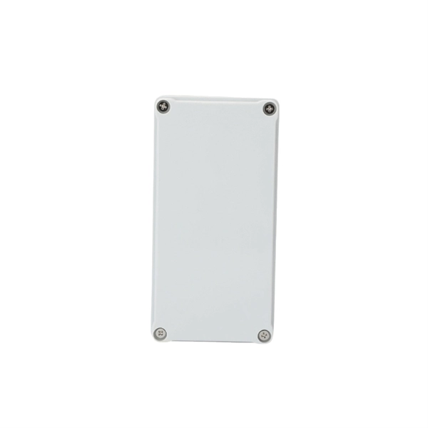
Start by examining the plastic cover closely to identify any tabs or locking mechanisms that may be holding it in place. This robust enclosure houses either the main service disconnect or a sub-panel, acting as a control point for electricity distribution to the property or a dedicated outdoor system like a pool or workshop. Gaining access to the panel's interior is usually necessary for simple tasks like resetting a. Opening electrical boxes outside can be a tricky endeavor. Without the proper tools, knowledge, and safety measures, it can also be dangerous. However, with a few simple steps, you can open an outdoor electrical box safely and efficiently. This is how you can open them to have access to the plug-ins. Once you've loosened the. This guide will explore the steps and considerations for safely and effectively punching out a plastic electrical box. Ensure the wires are not powered before starting work. Flat-head screwdriver, electrical pliers, hammer, and a suitable meter or tester. Locate. Before you attempt to open an outdoor breaker box, it's crucial to prioritize your safety. Here is a set of guidelines to ensure you undertake this task without any hazards: Confirm power is disconnected to the unit by turning off the main breaker or disconnecting the main fuse.
[PDF]

A protective relay is an intelligent electrical device designed to detect faults in power systems and initiate corrective actions such as tripping a circuit breaker. · Detection of the presence of a fault. · To close the trip circuit and operate the circuit breaker to isolate the faulty system from the healthier one. What is a protection relay? What is the purpose of protection. An electrically operated switch like a relay plays a key role in controlling an electrical circuit through an independent low-power signal, otherwise used where a number of circuits should be controlled through the single signal. Its main purpose is to safeguard electrical equipment like transformers, generators, and transmission lines from damage due to. A protection relay is a crucial component of electrical systems that safeguard infrastructure, employees, and equipment from electric problems and malfunctions. It functions as a watchdog by constantly surveying multiple system components including voltage, current, frequency, and phase angle. In other words, the prime function of protective relays is the timely and.
[PDF]

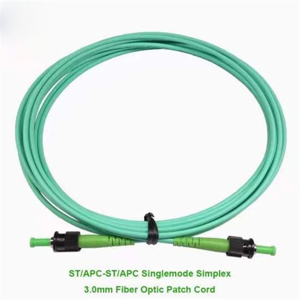
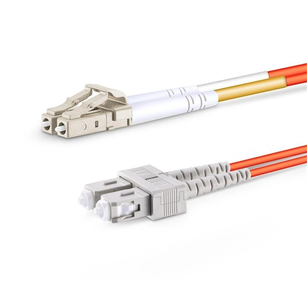
A fiber optic cable is a high-speed data transmission medium that carries information as light pulses through strands of glass or plastic fibers. Each strand contains a core and cladding that use total internal reflection to guide the light signal across long distances with minimal. What Does a Fiber Optic Cable Look Like? Fiber optic cables are often seen as the gold standard for network cabling. Unlike copper wires, which are limited by lower data transmission speeds, shorter transmission distances, and higher susceptibility to electromagnetic interference, fiber optic. A TOSLINK optical fiber cable with a clear jacket. These cables are used mainly for digital audio connections between devices. A fiber-optic cable, also known as an optical-fiber cable, is an assembly similar to an electrical cable but containing one or more optical fibers that are used to carry. A fiber optic cable is a data-transmission medium that uses light signals instead of electricity to transfer information. It consists of glass or plastic fibers surrounded by cladding, buffer, and protective layers. In the 1960s, modern optical fiber was created. This fundamental difference is why it's so fast and efficient. The process relies on a principle called Total Internal Reflection. Unlike copper cables, which depend on electrical signals, fiber.
[PDF]
The LEDs have three possible states: no light, a steady light, and a flashing light. Flashing lights may be slow, fast, or flickering. This light shows whether your ONT is getting power. Solid Green: The ONT is powered on and functioning normally. What to check: Make sure the power cable is securely plugged into both the ONT and a working wall outlet. If you're using a power strip, check. The tables in this article provide detailed information about the possible appearances of the LED lights on each device, the possible causes of each state, and what you should do. Ensure your Fiber Jack is connected to the network and the LED lights are connected and working properly before moving. System activity and status can be determined through the activity of the LEDs on the switch. A single tricolor LED for each SFP-DD indicates the port status. When the SFP-DD LED blinks white one time, it shows the status of the first port of the SFP-DD. An ONT may also be called a Service box. If you're having issues and can't get your ONT to power up, contact us. It flashes green during the initialization phase, remains solid green after successful initialization, and turns red when a system fault occurs. When the Status light is red, you can use a PC. Help Centre topics. Fibre ONT devices and how they work.
[PDF]
• Dims or switches most popular lighting sources and load types. • Available in one, two, and three-circuit Dimming Modules. Up to five Modules may be linked to obtain the necessary load capacity. • Accepts either 120V or 277V input power. Not compatible with 220-240V . Feed (input) circuits “feed through” to. Allows a wall dimmer or one zone on a GRAFIK Eye 3000 Series Control Unit to control loads of up to 30,000W/VA. • Dims or switches most popular lighting sources. NLight Air Wall Switch, On/Off, Raise/Lower Dimmer Control, 1 Pole, White, Generation 2 Compatibility Category: High Power Dimming Modules NLight Battery Powered Wall Switch Occupancy Sensor, On/Off & Raise/Lower Control, Color: White Category: High Power Dimming Modules LUT LMJ-16R-DV-B 434MHZ 16A. Most power LED drivers use a Switch Mode Power Supply (SMPS) design for their efficiency and small footprint. Nonetheless, most of these designs do not provide a mechanism for dimming, and those that do typically only provide linear current adjustment dimming. To provide stable color control, the. Provides four channels of technologically advanced, high-power universal dimming for 120 Volt residential lighting applications. Supports LED, incandescent, magnetic low-voltage, electronic low-voltage, and 2-wire dimmable fluorescent lighting loads. Installs in a CAEN or CAEN-MLO wall mount. Used to dim or switch heavily loaded zones.
[PDF]
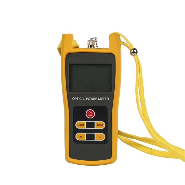
A spectrometer is a scientific instrument used to separate and measure components of a physical phenomenon. Spectrometer is a broad term often used to describe instruments that measure a continuous variable of a phenomenon where the spectral components are somehow mixed. In a spectrometer can separate white and measure individual narrow bands of color, called a spectrum. A.
[PDF]
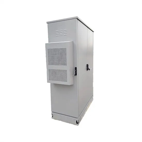
Connect the phase and neutral wires from the input power supply to the input of the Main MCB. If you use a DP MCB for output load then connect both phase and neutral from the output of the RCCB to the input of the Load. This guide provides step-by-step instructions for connecting a distribution box and highlights key factors to consider during installation. What Is a Distribution Box? A distribution box, also known as an electrical distribution board, is a critical component in electrical systems. It serves as a central hub for distributing electricity throughout a building, ensuring that power is delivered safely and efficiently to all the required locations. It is usually equipped with circuit breakers, fuses, terminal connectors, and other components. It is mainly used to isolate fault circuits, prevent overload, and ensure the safe operation of. How to wire a household distribution box? How to pg clamps. When it comes to decoration, many friends like to do it themselves. However, when encountering water and electricity and other links that have a greater impact on the overall decoration, you must do your homework and not implement it. In this video, we'll walk you through the process of wiring a home distribution box with a detailed connection diagram. Whether you're an electrician or a DIY enthusiast, this guide will help you understand the basics of home electrical distribution.
[PDF]

Arduino-Powered Data Transmission with Fiber Optics Welcome to our video tutorial on optical communication with Arduino, designed to be easy t. more. They consist of a transmitter on one end of a fiber and a receiver on the other end. Most systems use a "transceiver" which includes both transmission and. I'm going to use HFBR 1414 fiber optic transmitter module which is manufactured by Broadcom. It is a low-cost high-power transmitter that is designed for use in industrial power generation, power distribution, medical transportation and gaming applications. Internally, the optical fiber consists of a highly reflective central core, which acts like a light guide. Media converters are special fiber optic transceivers used to convert from one type of cable (the media) to another, typically from copper cables to fiber optics, although some media converters will convert from one fiber type to another, e. multimode to singlemode. The FOA Guide has a page about. A fiber optic transceiver (also called an optical transceiver) is a compact module that both transmits and receives data signals through optical fibers. It serves a dual purpose — transmitting electrical signals as light pulses and receiving light pulses to convert them back into electrical form.
[PDF]
This visualization shows the growth of the undersea cable network, global internet peering capacity, and the distribution of IP addresses via BGP announcements over time. Use the controls at the top to play the animation or step through year by year. The Submarine Cable Map is a free and regularly updated resource from TeleGeography. TeleGeography's comprehensive and regularly updated interactive map of the world's major submarine cable systems and landing stations. For more details and insights, please read this. Dongguan TW-SCIE Co.,Ltd is a professional manufacturer of FTTH drop cable, indoor/ outdoor fiber optic cable and patch cord. Products are conform to ISO 9001 standard. Welcome to visit us: Krasnopresnenskaya Naberezhnaya, 14. Dongguan Guanhong Optical Cable Co., Ltd (referred as Fiberplan) is a high-tech enterprise integrating the research, manufacture and marketing. And we can produce customized products as customer's require. The facility commenced operations in 2003, and its purpose was publicly revealed by AT&T technician Mark Klein in 2006. Room 641A is located in the SBC Communications building at 611 Folsom Street, San Francisco, three floors of which were occupied by AT&T before SBC purchased AT&T.
[PDF]
Electromechanical protective relays at a hydroelectric generating plant. The relays are in round glass cases. The rectangular devices are test connection blocks, used for testing and isolation of instrument transformer circuits.OverviewIn, a protective relay is a device designed to trip a when a is detected. The first protective relays were electromagnetic devices, relying on coils operating on moving par. Electromechanical protective relays operate by either, or. Unlike switching type electromechanical with fixed and usually ill-defined operating voltage thresholds. Electromechanical relays can be classified into several different types as follows: "Armature"-type relays have a pivoted lever supported on a hinge or knife-edge pivot, which carries a moving contact. These relays may.
[PDF]
Attach a ground wire from one of the threaded studs (A) at the bottom of the housing, to the mounting plate (B). The ground resistance between all system parts shall be <. The protective grounding system, which includes conductor grounds and worker bonding, must be engineered to protect workers from hazardous voltages that can be created by line reenergizing, lightning, or induced oltage. If more than one crew is working independently on the same deenergized line or. Power from factory ground must be installed by a qualified electrician. Each DISTRIBUTION BOX and controller must be grounded. On the US market, a 5. 26 mm 2 (10 AWG) ground wire must be used, and in all other markets a 6 mm 2 must be used. The neutral conductor is typically the grounded conductor connected to the system's neutral point, carrying current under normal operation. Grounding electrode conductors must be connected at. The correct connection method of Distribution box grounding wire mainly includes the following steps: 1. Whether you're a seasoned pro or just starting out, this comprehensive guide will give you practical. This technical article covers protective grounding requirements for steel tower and wood pole supported transmission and distribution lines, and insulated power cables. Protective grounds must be installed so all phases of lines or cable are visibly and effectively bonded together in a multi-phase.
[PDF]

This helps keep fiber optic cables safe from harm and signal problems when you put them in. Use the right lubricant. Follow the rules for tension and bend radius. Try new methods like air blowing. Use smart. Fiber optic cable is surprisingly strong, durable and pliable; however, several best practices should be followed to ensure a successful cable installation. This article explores recommendations for pulling and installing fiber optic cable. This makes sure the cable pull is smooth and safe. Use smart monitoring devices. The Future Ready Solutions Tools & Test. A duct is available from point A to point B, a pull tape is blown in, a fiber optic cable is attached to it and the cable is pulled through the duct. Sounds simple, doesn't it. Recent observations and conversations with more than a few people in the fiber optic business have indicated. Route plan to ensure the duct run maintains the minimum bend diameter of the cable. For more information and all recommendations for installation, refer to Corning Optical Communications Standard Recommended Procedure SRP 005-011, "Duct Installation of Fiber Optic Cable". more Route plan to ensure.
[PDF]