In this video, we'll walk you through the process of wiring a home distribution box with a detailed connection diagram. Whether you're an electrician or a DIY enthusiast, this guide will help you understand the basics of home electrical distribution. more Welcome to our. Learn how to install a distribution box safely and correctly. Covers wiring, placement, standards, and expert tips for a compliant setup. A distribution box is the heart of any electrical system. It takes the incoming power and safely distributes it to different circuits throughout your building. And all the switching and protective devices are installed in the. How to Estimate the Size of the Box that I Want? Can I Customize a Distribution Box? How to Choose a Suitable Electrical Distribution Box? How does a Distribution Box Work? What's the Difference Between Distribution Boxes and Junction Boxes? What is the recommended inspection schedule for. In this video, we'll walk you through the process of wiring a home distribution box with a detailed connection diagram. more Welcome to our channel! In this video. A distribution box, also known as a distribution board, electrical panel, or breaker box, is an enclosure that houses electrical components responsible for distributing electricity throughout a building. It serves as a central hub for distributing electricity throughout a building, ensuring that power is delivered safely and efficiently to all the required locations.
[PDF]
Answer: The current transfer ratio (CTR) is an important parameter in optocoupler selection. The gain of an optocoupler is expressed as the Current Transfer Ratio (CTR). It is defined as the ratio of the phototransistor output current (Ic) to the LED input current (If), expressed as. The current transfer ratio is a parameter similar to the DC current amplification ratio of a transistor (h FE) and is expressed as a percentage indicating the ratio of the output current (I C) to the input current (I F). The CTR has the following characteristics and is therefore as important as the. An optocoupler, also known as photocoupler or opto-isolator, is a device which can transfer an electrical signal across two galvanically-isolated circuits by way of optical coupling. Transferring signals over a light. As I understand the optocoupler current transfer ratio, CTR is like the hfe of a transistor. I can't understand if the CTR is or isn't a critical value and for what applications is it used in. Optocouplers contain both a light-emitting diode (LED) and a photo detector. The current transfer ratio. The current transfer ratio (CTR) refers to the ratio of the collector current at the output side I c to the input current passed to the LED at the input side I F expressed as a percentage. It is defined by the following formula.
[PDF]
View result: The primary current will be displayed instantly in Amperes. Tips for better accuracy: Always use correct units (kVA, volts). Double-check voltage values. Choose the correct phase system. The formula depends on the transformer type. Primary Current (I) = Power (VA) / Voltage. The primary formula for calculating current in a single-phase AC circuit is derived from the relationship between power, voltage, current, and power factor: This equation assumes a sinusoidal waveform and is applicable to resistive and inductive loads. To simplify calculations, constants can be. Input primary voltage: Enter the input voltage in Volts (V). Select phase type: Choose between single-phase or three-phase. Click calculate: Press the button to get the result. It is easy to visualize the current flowing out of a battery, through a light bulb, and back to the battery. There is a voltage rise across the. It involves using a straightforward formula to generate your kVA requirements from the current and voltage of your electrical load. In the guide to transformer kVA ratings below, we'll explain in more detail how to calculate the required capacity kVA rating. Electricity is carried from the transmission system to individual consumers. Distribution substations connect to the transmission system and lower the transmission voltage to medium voltage ranging between 2 kV and 33 kV.
[PDF]
Finally, use the following formula to determine the busbar current. Calculate the current carrying capability of a 150 (width) x 25 (thickness) (in mm) busbar in the copper material. 2 Ibb = 4500A Click here for more Electrical Calculators IEC 60865-1:. Copper busbar current carrying capacity (ampacity) is the maximum electrical current a copper busbar can safely conduct without overheating or failure, a critical parameter for electrical panel and power distribution design. 2 and IEC 60364 standards ensures copper busbar. To calculate Busbar Current, enter the width (mm), thickness (mm), and material carry capacity factor (amps/mm^2). The electrical power system consists of many incoming & outgoing feeder connections, for which busbars are necessary. A busbar is just a node (conductor or collection of conductors). Even though a busbar looks like just a flat copper or aluminum strip, its size determines how much electrical load it can handle. If the size is too small, it can overheat, cause voltage drop, or even become a fire hazard. If it is oversized, it increases cost and space requirements unnecessarily. Busbars are critical components in electrical distribution networks, typically used to distribute high current among various circuits. 2 A/mm² for copper busbars in enclosed panels and up to 2. 2 Copper busbars have approximately 60% higher current carrying capacity than.
[PDF]
A spot network typically comprises a secondary network that serves a singular, concentrated load, such as a high-rise building or shopping mall, necessitating a high level of reliability. The secondary spot netw.
[PDF]
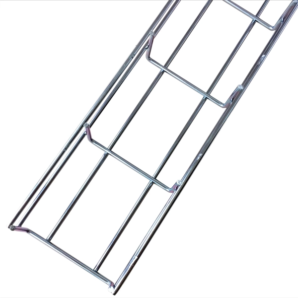
Cable tray may be used as the Equipment Grounding Conductor (EGC) in any installation where qualified persons will service the installed cable tray system. There is no restriction as to where the cable tray system is installed. The metal in cable trays may be used as the EGC as per the limitations. Cable tray wiring systems have excellent safety and dependability records. If you take what UL states literally, ANY cut to tray (ladder or wi e) would cause a loss of UL Classification. For example, when a straight section of tray is cut to length and used in conjunction with a factory fitting — this installation would also. An Equipment Grounding Conductor (EGC) refers to a safety wire or a metal conductor that transfers the so-called stray electricity back to the power source in case of a problem. Consider it as an emergency electricity exit. Grounding: Metallic trays can serve as equipment grounding conductors (EGC) if they meet NEC requirements. Fill Limits: For power cables, the fill must not exceed 40% of the tray's.
[PDF]

When designing a cable tray wiring system, the designer should evaluate the National Electrical Code's (NEC) Equipment Grounding Conductor (EGC) options that are applicable for the project. Use the cable tray as the EGC. The metal in cable trays may be used as the EGC as per the limitations. Cable tray grounding wire is the safety connection that links your electrical system's cable tray to the ground. This provides a safe path for any stray electrical currents to flow safely into the earth, avoiding damage to your equipment and reducing the risk of electric shocks. EGCs are a critical component in electrical infrastructure, ensuring safety and compliance by providing a low-impedance path to. that system to lose its UL Classification. If you take what UL states literally, ANY cut to tray (ladder or wi e) would cause a loss of UL Classification. For example, when a straight section of tray is cut to length and used in conjunction with a factory fitting — this installation would also.
[PDF]

In a metal box, a wire type equipment grounding conductor can be attached to the box with a ground screw or clip and terminated to the switch or receptacle in the box. Connecting the receptacle grounding terminal to the metal box ensures an effective ground-fault current path. The basic rule achieves this through an equipment grounding jumper; four exceptions. A main bonding jumper is required to bond the service disconnect enclosure to the service neutral conductor [250. Not all boxes are metal or provide. The main bonding jumper bonds the neutral conductor to the equipment grounding conductor, enabling proper operation of overcurrent protective devices. Neutral conductors must be properly sized based on the load and installation method, with specific requirements for conductors in parallel or. According to the National Electrical Code (NEC), this connection is made between the grounded conductor (typically the neutral) and the equipment grounding conductor (EGC) system at the service equipment. Proper location and sizing are not just best practices; they are essential for ensuring that. NEC Article 250 is dedicated entirely to grounding and bonding, outlining the specific conductors and connections required. Grounding Electrode Conductor (GEC): This is the wire that connects the grounding electrode (the rod) to the grounding bus bar in the main electrical panel.
[PDF]