In this video, we'll show you how to connect an energy meter to a distribution board (DB) safely and efficiently. energy meter connection with distribution box How to Connect an Energy Meter to Your Distribution Box Easily Steps to Properly Connect Your Energy Meter to a Distribution Box. It plays a vital role in ensuring the safe and efficient distribution of electricity throughout the premises. What is the wire from the meter to the breaker box? Also. Always begin with disconnecting the main supply before accessing any enclosure containing distribution components. This prevents arc faults and ensures safety when modifying or inspecting current paths. This “meter to panel” wiring establishes the pathway for all incoming electrical power from the grid to the home. Its primary function is to safely and reliably. Distribution Board aslo know as “Panel Board”, “Switch & Fuse Board” or “Consumer Unit” is a box installed in the building containing on protective devices, such as circuit breaker, fuses, isolator, switches, RCDs and MCBs etc. The electric main supply (230V AC & 120V AC in US) is connected through. Changed Texas's reference diagram for the 3 wire network 120/208 Volt single phase self-contained Revised Figures 13, 14, 14b. Limited the meter location from pad mount transformer for PSO. Removed unistrut being listed as an alternative means for mounting the meter box. APCo and TX do not allow.
[PDF]

Select the correct wavelength and set your reference. You measure optical power in dBm or insertion loss in dB. Consistent procedures ensure accuracy. Measure total signal loss from fiber, connectors, or splices. Optical fiber attenuation is the attenuation per unit length of optical fiber, and the unit is dB/km. When connecting two optical fibers, there will be loss inside any connector or joint. Consistent measurement techniques. While optical power meters are the primary power measurement instrument, optical loss test sets (OLTSs) and optical time domain reflectometers (OTDRs) also measure power in testing loss. TIA standard test FOTP-95 covers the measurement of optical power. Optical power is based on the heating power. Light Source: The CMA5 Series Light Sources provide an economical and stable laser source for use in point-to-point attenuation measurement. They feature a rugged design, built to withstand the difficult testing environment of fiber optic cable installation and maintenance. The CMA5 Light Sources. When talking about optical measurements, wavelength basically means how far a wave pattern repeats itself, usually measured in nanometers (nm). Commonly, a power meter on its own is used to measure absolute.
[PDF]
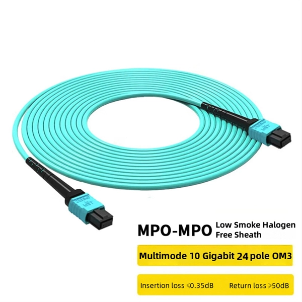
Fiber optic cable installation costs average $4,500 for most homeowners, with most installations ranging from $1,500 to $7,000. Computer repair costs depend on your project and location. Check with a local pro for your specific job. The installation type you choose and the layout of your. Homeowners and businesses typically pay for fiber optic cable installation based on distance, conduit needs, and labor. The main cost drivers include material type, run length, trenching or aerial work, and any required permits or inspections. This guide provides clear cost estimates, price ranges. Fiber optic cables consist of multiple fibers, each designed for high-speed data transmission. These fibers are thin strands, often as small as a human hair, that transmit data as pulses of light. Data aggregated from Q1 2026 contractor invoices across Texas, Ohio, and North Carolina.
[PDF]
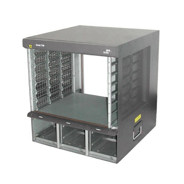
Here you can download the program for the configuration of our electrical cabinets. Written by Schneider Electric's most talented electrical distribution experts, the Electrical Installation Guide is written for professionals who design, install, inspect, and maintain low-voltage electrical installations in compliance with the standards published by the International. Perhaps you need to minimise heat losses to air in a facility without air-conditioning? Many of our most popular DC and AC power systems can be built into IP54 cabinets. An IP54 level of Ingress Protection provides a high level of protection against non-conductive airborne pollutants. Used to house electrical or electronic switchgear, control gear and equipment. The PDU series is designed to meet the needs of power distribution units of telecom access sites. It comes with an integrated controller that enables customer to read tenant-wise energy statistics as well as to extend the remote monitoring access. It is flexible enough to mount in the different. This Electrical Installation Wiki is a collaborative platform, brought to you by Schneider Electric: our experts are continuously improving its content, collaboration is also open to all. DC power is typically used in Data Centres and telecom facilities as it has several benefits. Firstly, DC power can be more efficient than AC power systems as the need for AC to DC conversion is.
[PDF]

The core measurement procedure follows five steps: Turn on the meter and let it warm up. Most meters need a brief stabilization period before readings are reliable. Check your model's manual, but a minute or two is typical. Set the wavelength to match your light source. Fiber loss is the difference between the power when light is coupled from the transmitting end to the fiber and the power when the light reaches the receiving end. Generally speaking, when measuring the. An optical power meter measures the strength of light traveling through a fiber optic cable, giving you a reading in dBm (decibels relative to one milliwatt). The basic process is straightforward: turn the meter on, set it to the correct wavelength, clean your connectors, plug in, and read the. A power meter and light source are essential test tools that work in tandem to measure fiber optic cable loss and evaluate the quality of optical links. They provide the data necessary to quantify signal loss and pinpoint issues that could impact network performance. Here's how they work: A power. You measure optical power in dBm or insertion loss in dB. Verify light travels from transmitter to receiver. We'll give you the basic information you need and provide some printable references.
[PDF]
In 1880, and his assistant created a very early precursor to fiber-optic communications, the, at Bell's newly established in. Bell considered it his most important invention. The device allowed for the of sound on a beam of light. On June 3, 1880, Bell conducted the world's first wireless transmission between two buildings, some 213 meters apart. Due to its use of an atmospher.
[PDF]

The OPM 510 and 520 are available in standard and high-power versions for the Telco and MSO markets. The OPM510 and OPM520 supports wavelengths of 850, 980, 1270 1300, 1310, 1490, 1550, 1577, 1623 and 1650nm. The rugged enclosure provides confidence when testing singlemode and. Count on Tempo Communications Optical Power Meters (OPM510/520) to test and maintain your fiber optic networks. Our optical power meters feature built-in calibration factors. Optical power meters and detectors have been served by Newport for over 30 years. The offering ranges from a low cost, hand-held meter to the most advanced dual channel benchtop power meter available in the market. Our 1936-R/2936-R series boasts state-of-the-art analog boards with a whopping 250. © Copyright© Santec Holdings Corporation. Demo the full range, from multi-use to dedicated PON and FTTH. VIAVI offers fast, cost-effective, and easy-to-use power meters for installation and maintenance of single mode and multimode fiber optic networks and. AFL is a trusted supplier of optical testing equipment with more than 30 years of experience and tens of thousands of units in use in the field. AFL's full range of power meters are used for testing single-mode and/or multimode fiber networks. Power meters with wave ID can detect two or more.
[PDF]

How to Use Optical Power Meter TR-504 | Optical Power Meter Working| Testing OPM, VFL, RJ45 | TRICOM In this video, we walk you through how to use the TRICOM TR-504 Optical Power Meter and explain how it works. Learn how to test fiber optic cables, OPM, VFL . Optical power meters are a key element in the optimization and maintenance of such optical networks and of their components. In this article, learn: What is an optical power meter? An optical power meter (OPM) measures the power levels of light signals in devices that transmit data or power using. An optical power meter measures the strength of light traveling through a fiber optic cable, giving you a reading in dBm (decibels relative to one milliwatt). The basic process is straightforward: turn the meter on, set it to the correct wavelength, clean your connectors, plug in, and read the. OPM interface: insert the fiber to be tested, test the optical power. An optical power meter is a tool that measures the number of optical power in a cable is fiber-optic. It helps engineers verify the performance of optical fiber systems, ensuring that the signal strength meets requirements, and is an essential tool for communication network maintenance and troubleshooting.
[PDF]

Here's a comprehensive guide to the 15 best optical power meters for fiber techs in 2025, offering expert insights and reviews to help you find the perfect tool for your needs. Also, please take a look at the list of 26 optical power meter manufacturers and their company rankings. Novanta Photonics, 3. What Is an Optical Power Meter? What Is an Optical Power Meter? An optical. | | | | | |. Optical power meters measure the average optical power (energy per unit time) of continuous-wave (CW) or high-repetition-rate pulsed light sources. They are distinct from optical energy meters, which measure the energy of single light pulses, although some consoles support both sensor types. They. Optical power meters and detectors have been served by Newport for over 30 years. The offering ranges from a low cost, hand-held meter to the most advanced dual channel benchtop power meter available in the market. Our 1936-R/2936-R series boasts state-of-the-art analog boards with a whopping 250. HPC-50BVhandheld optical power meter has compactsize and high reliability. It can make accurate measurement on seven operating wavelengths (850/980/1300/1310/1490/1550 /1625nm). ST800K-UC SC/ST/FC Li battery with USB, -70~+10 dbm optical power meter. Optical Power Meters from ADC Corporation are listed on GoPhotonics. Use the filters to.
[PDF]

It consists of 5 buttons. A power button, a button to turn on the VFL, a lambda button to set the wavelendth, a REF button, and a dBm/W button to set the unit of power. First, you check the initial power of a light signal. Then you check its power at the other end of optical. OPM interface: insert the fiber to be tested, test the optical power. REF/dB key: Short press the dB to switch unit, click once nW/dBm/dB to enter the upper clear data, press and hold until REF is displayed on the screen, and set the current optical power as reference value, enter the relative. There are two buttons on this meter. One is the power button, used to turn the meter on/off. At the top, there is a sensor that detects the light beam. The. at -22 (or 25 with tone on)). To do this you. Active Equipment Power Measurement Fiber Continuity Patch Cable Testing Check MM Reference Cables - Dual OWL MM Sources Check MM Reference Cables - WaveSource MM Sources Check SM Reference Cables - Laser OWL SM Sources Check SM Reference Cables - WaveSource SM Sources. Power-off: Press and hold “MODE” key for 2 seconds or more until “OFF” displays on the screen. Note: This instrument will shut down automatically without receiving any operation instruction for 10 minutes. Function selections: It.
[PDF]
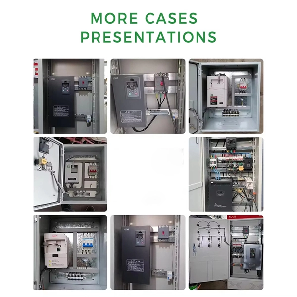
In this guide, we'll break down everything you need to know to install a distribution box correctly and confidently. Choose the right box based on environment (indoor/outdoor), load capacity, and durability. Check for proper IP/NEMA ratings and material quality. This section includes guidelines for the construction, installation, and inspection of electrical systems. Review Part 4, “Highway Traffic Signals,” of the California Manual on Uniform Traffic Control Devices; California Code of Regulations, Title 8, “Electrical Safety Orders,” (8 CCR 2299 et. The QUAZITE® H20 enclosures include a rugged polymer concrete box with a galvanized steel frame and cover surrounded by a minimum of 3 inches of cast-in-place concrete. For scenarios that could benefit from this type of enclosure, read our blog. When is a roadway like a bridge? Any underground. Learn how to wire a distribution box step by step! This video shows real on-site footage of electrical installation, demonstrating safe and standardized wiring methods used by professionals. Covers wiring, placement, standards, and expert tips for a compliant setup. It takes the incoming power and safely distributes it to different circuits throughout your building. the shoulder surface. Restore the disturbed area around the pull box and m cover of 12 inches. Otherwise, provide a minim.
[PDF]
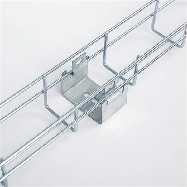
Choose the right box based on environment (indoor/outdoor), load capacity, and durability. Check for proper IP/NEMA ratings and material quality. Ensure safe placement: install in dry, accessible areas with good ventilation and at appropriate height (typically ~1. In this guide, we'll break down everything you need to know to install a distribution box correctly and confidently. Necessary materials include an electrical enclosure, expansion bolts, fixing brackets, screws, terminal blocks, qualified wires, cable ties, insulating tape, etc. Inspect all of them. This video provides valuable insights for anyone looking to improve their electrical wiring skills and ensure safe and reliable power distribution. In modern electrical systems, cable distribution boxes (also known as electrical distribution boxes or distribution boxes) play a crucial role as the key hub for managing, distributing, and protecting circuits. Whether it is residential buildings, commercial facilities or industrial sites, the. A distribution box, also known as a distribution board, electrical panel, or breaker box, is an enclosure that houses electrical components responsible for distributing electricity throughout a building. It serves as a central hub for distributing electricity throughout a building, ensuring that power is delivered safely and efficiently to all the required locations.
[PDF]

PC configuration software for Reyrolle products including Reydisp Manager 2, Reydisp Manager 1, and Reydisp Evolution. Doble RTS™ (RTS) is the premier protection testing software system for improving the work of testing relays and managing test records. Process consistency with power and flexibility set RTS software apart, and tremendous automation enables unmatched efficiency, accuracy and productivity. Apply your. Download documents, support information, software, video and audio content. IEC61850 Digital Substation Testing With 15 years experience in IEC61850 digital substation testing, KINGSINE portable relay testers are designed for comprehensive testing in both traditional and digital substations, including MU and IEC61850 compliant IEDs. Protection Relay Test Set/Kit KINGSINE. The commissioning of protection systems is an essential step to ensure the safety, reliability, and operational efficiency of electrical installations. In this context, the testing of protection relays and IEDs (Intelligent Electronic Devices) must be carried out with maximum precision, speed, and. A software designed to manage all aspects of protective relay testing using the Megger SMRT and FREJA models of relay testers. Facilitates steamlined and efficient relay protection testing through automation and relay modules. By using one of the over 400 relay templates with relay settings import. Portable at just 15 kg, the FREJA 300 is intended primarily for.
[PDF]

In this guide, we'll break down everything you need to know to install a distribution box correctly and confidently. Choose the right box based on environment (indoor/outdoor), load capacity, and durability. Check for proper IP/NEMA ratings and material quality. Ensure safe placement: install in. This method statement will help the electrical engineers and supervisors for the installation of distribution board for an electrical project. Additionally site team will need detailed information of all aspects associated with the installation process in order to complete the job inline with the. h error or omission is the result of negl ion for commercial installations has changed in the last few years. There is a demand for more RCD protection of final circuits, affect Type B MCB distribution boards and their protective d bar arrangement designed to accept single and/or double pole OCPDs. ntact Cooper Lighting Customer Service at 1-800-573-3600. The most up to date version of this insta ecification sheet for weight and wind loading (EPA) data. Cable glands and lugs, 2. Applicable Location 3. Respective electrical rooms, LV. Installing a distribution box is a crucial step in the setup of a septic system, serving as the central hub that directs wastewater from the septic tank to the drain field. This component ensures that effluent is evenly distributed across the leach field, preventing overloading and potential system.
[PDF]
This video shows real on-site footage of electrical installation, demonstrating safe and standardized wiring methods used by professionals. Whether in a home or an industrial facility, this box keeps your electrical setup organized, functional, and efficient. However, the key to a safe and reliable system lies in proper installation. If it's done poorly, you risk short circuits, fire hazards, or system failure. Done right, it ensures. Whether you are an electrical contractor or a construction brigade, knowing how to properly and safely install distribution boxes is the basis of ensuring the safe operation of the entire system. This article details the process of installing them, which helps you comprehend distribution boxes. How to Install a Cable Distribution Box Safely and Correctly? In modern electrical systems, cable distribution boxes (also known as electrical distribution boxes or distribution boxes) play a crucial role as the key hub for managing, distributing, and protecting circuits. Can I convert the circuit wiring in my shop to be used for different equipment? Converting Existing Circuit Wiring in a Workshop or Garage. There is a demand for more RCD protection of final circuits, affect Type B MCB distribution boards and their protective d bar arrangement designed to accept single and/or double pole OCPDs.
[PDF]