An optical line termination (OLT), also called an optical line terminal, is a device which serves as the service provider endpoint of a passive optical network. It provides two main functions: to perform conversion between the electrical signals used by the service provider's equipment and the fiber optic signals used by the passive optical network.to coordinate the multiplexing between the conversion. FeaturesOLTs include the following features: • A downstream frame processing means for receiving and churning an cell to generate a downstream frame, and converting a parallel dat. Most vendors integrate an entire fiber optic management system for ISPs to manage OLTs as well as client ONTs and as such are not interoperable. • • BT-PON.
[PDF]

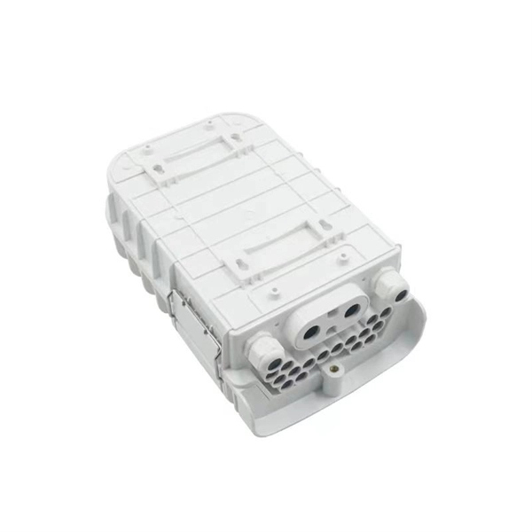
Explore verified suppliers, compare prices from $183–$2,500, and discover top-rated products with 16 port capacity, GPON compatibility, and customizable options. Click to find the best fit for your network needs. We use cookies or similar technologies to ensure this website functions properly, analyze traffic, or optimize your experience. Continuing to browse this site indicates your agreement to use these cookies. Learn More Tenda Optical line terminals, also called optical line terminations (OLTs), serve. At the heart of a point-to-multi-point or passive optical network (PON) is the optical line terminal (OLT). Modern OLTs offer communication service providers (CSP) the ability to launch multigigabit services to tens of thousands of subscribers from a single location or just ten. Fiber-to-the-home. FlexSym Optical Line Terminal Two (OLT2) The Tellabs FlexSym® OLT2 Optical Line Terminal is a multi-purpose Optical Line Terminal (OLT) enabling open, simple, and scalable connectivity for wired and wireless networks over fiber and copper networks. Our silicon devices have been interoperability-tested, field-proven and adopted by various worldwide operators and carriers. 2065 olt ftth optical line terminal products are offered for sale by suppliers on Alibaba. com, of which fiber optic equipment accounts for 85%. Explore our range of high-quality GPON, EPON, and XG (S)PON OLT products.
[PDF]

In simple terms, Receiver Sensitivity is the minimum received optical power required at the input of a receiver for the system to achieve a specified performance level, typically defined by a maximum Bit Error Rate (BER). Think of it like listening to a distant radio station. The standards body governing the application sets this specified BER. For example, SONET specifies that the BER must be 10 -10 or better. Optical modules form the backbone of modern data center networks, enabling ultra-high-speed data transmission between servers, switches, and storage devices. In optical link design, the receiver performance parameters are like vital signs of the link, directly determining the reliability and. Receiver sensitivity shows the weakest signal your device can find. Good sensitivity gives stronger connections, even with weak signals. Always look at the dBm value in product details. A lower dBm means better receiver sensitivity. This helps you pick the best device. It denotes a module's capability to function in challenging environments and aids network operators in determining the system's maximum reach or link margin.
[PDF]
If your high beams are not working, the most likely cause is a blown fuse or a burned-out bulb — both of which you can check yourself in under 15 minutes. That said, there are seven possible culprits, ranging from simple fixes you can handle at home to electrical faults that need a mechanic's. To be clear, I am not saying the highbeams are turning on and off, I mean the actual intellibeam system as indicated by the headlight symbol with the "A" in it on the DIC. When the system is on, the highbeams most of the time will work 100% as expected activating and deactivating when appropriate. Automatic high beam (AHB) systems, sometimes marketed under proprietary names like IntelliBeam or SmartBeam, are designed to enhance nighttime visibility by automatically switching between high and low beams. These systems use forward-facing cameras or sensors to detect light sources from oncoming. Affiliate programs and affiliations include, but are not limited to, the eBay Partner Network. 2021+ Ford F150 Discussion of the 14th generation F150. LED headlight High Beam Failure noticed that high beam on the drivers side LED headlight stopped working. Hooked up the reader and found fault code. Auto High Beam is a safety feature that controls the headlight operation and lights up the road in front using low and high beams. There is too much lag time for enabling the high beams. I just use the old skool manual headlights mode and switch my high beams as.
[PDF]

Optical Modules are hot swappable, and you do not need to power off the device when replacing Optical Modules. Optical Modules are electrostatic-sensitive components. In most enterprise networking environments, the ability to replace hardware without shutting down equipment is essential for maintaining uptime. Do not insert an optical module reversely. Gently pull the module latch or release ring, depending on the module design. Remove the module in a straight motion – do not twist or pull at an angle. Reapply the. Before you begin removing a transceiver from the router, ensure that you have taken the necessary precautions for safe handling of lasers (see Laser and LED Safety Guidelines and Warnings). Ensure that you have the following parts and tools available: The transceivers for the router are. An optical module implements optical-electrical conversion, enabling optical transmission between a DRH and other devices. Disconnecting the optical fibers interrupts the transmission of CPRI signals.
[PDF]

In the photopic region, luminous efficacy peaks at 683 lumens per watt at 555 nm. In fact, the lumen is defined in terms of the power at 555 nm (frequency of 540 × 1012 Hz). Luminous efficacy is defined as the luminous flux produced per unit of power, usually electrical power, measured in lumen per watt (lm/W). It is explained how the overall efficacy of a lighting installation is often lower than that of the light source itself due to factors like light absorption in. Luminous efficacy is a measure of how efficiently a light source produces visible light. Depending on context, the power can be either the radiant flux of the source's output, or it can. The relative spectral responsivity of the human visual system was first defined by the Commission Internationale de l'Éclairage (CIE, the International Commission on Illumination) in 1924. The response of the eye as a function of frequency is called the luminous efficacy of the eye. It has been tabulated for both the light-adapted (photopic) case and the dark-adapted (scotopic) case. Source: Table 6-1 of.
[PDF]

In this tutorial, I will show you how you can connect the Optocoupler to Arduino, read the data as Analog or Digital, and if necessary convert the analog values to digital, and how to reduce noise from the sensor. The Infrared Slotted Optical Optocoupler Module is a device that uses infrared light to transmit signals between two electrically isolated circuits. It consists of an infrared emitter (LED) and a photodetector (phototransistor) housed in a slotted enclosure. When an object passes through the slot. Slotted Optocouplers (Photo Interrupters) are very useful sensors, often included in Arduino projects to detect position of moving objects, measure speed of rotation, or linear motion, frequency of events, and many others. They are easy to use, but it is important to understand how they work, so. This tutorial is a comprehensive, practical guide to the Speed Sensor / Tacho Sensor (Slot-Type Optocoupler) (Leobot Product #245). Moreover, a simple application is programmed that shows how to wire and how to program an Arduino when working with the module. In this tutorial, the module is used as an “digital input board”. If you want to use the. In this project, I will talk about Phototransistor Optical Interrupter Switches (Opto Coupler) Module, how this module works and helps in determining the speed of a rotating object and finally I will show you how to Interface Optical Interrupter Switch Sensor with Arduino and measure the speed of a.
[PDF]

This publication shows how to wire and install the 4010-9825 24V Distribution Block into a 4010 Fire Alarm Control Panel (FACP). Refer to the 842-058 Field Wiring Diagram for additional wiring information. 1 Transformer connection: Two red wires connect to AC 220V input port, while two yellow wires connect to AC input port of main board (had connected by the factory. 2 DC12V battery connection: Red wire on the circuit main board connects to the positive pole of acid-lead battery while black. Notify the carrier and call Telect's Customer Service Department at 1-800-551-4567. Keep the container until you have checked equipment operation. Use the original, undamaged container if you are instructed to return. Learn how to wire a distribution box step by step! This video shows real on-site footage of electrical installation, demonstrating safe and standardized wiring methods used by professionals. Such a system, however, does not assure. Material preparation: Prepare the required circuit breakers, wires, wiring ties and other materials, and ensure that they meet the design drawings and installation requirements. Location determination: Determine the installation position of the circuit breaker according to the position of the.
[PDF]

Continuous-wave operation (cw operation): The laser is continuously pumped and emits light continuously, either on a single resonator mode (→ single-frequency operation) or on multiple modes (see also: single-mode operation). How do optical. EML stands for Externally Modulated Laser (corrected from "External Modulated Laser"). Its basic principle is to supply a constant current to the laser diode, ensuring the LD emits continuous, stable light. An external electro-absorption modulator (EAM) then adjusts light transmittance to generate. A wavelength swept light source emits laser light with a continuously sweeping wavelength. It is suitable for shape measurement and displacement measurement utilizing OFDR (Optical Frequency Domain Reflectometry), an optical sensing method using the coherence of laser light. The transmitting interface inputs electrical signals of a certain bit rate, which are then processed by internal driver chips. Subsequently, the driver semiconductor laser. Industry pundits have recently speculated that demand for 100G/400G switches may take off in 2019, prompting optical transceiver module vendors to sample data center switches with high data transmission rates earlier than expected. As data center operators accelerate upgrades in preparation for 5G.
[PDF]

Bit Error Rate (BER) is a critical performance metric in optical communications that measures the number of errors occurring in a transmitted data stream over a certain period. It is defined as the ratio of the number of bits received in error to the total number of bits transmitted. This ratio is most often expressed using scientific notation (e., 10⁻⁸. USI has industry-leading capabilities in high-speed signal integrity and power integrity (SI/PI) design, as well as advanced thermal simulation and optical simulation using Zemax. In addition, we have strong expertise in high-speed PCB design utilizing mSAP and substrate PCB technologies. USI also. Unlock AI-driven, actionable R&D insights for your next breakthrough. As optical links are increasingly used for high-speed data. Even a digital data transmission system is not totally error-free — statistical fluctuations related to noise influences cause a small percentage of the transmitted bits to be corrupted. The average fraction of incorrectly transmitted bits is called the bit error rate. Offers precise, cost-efficient optoelectronic signal and anomaly testing for high-speed transceivers. · Use control board and replaceable.
[PDF]

Wavelength: 1310nm, 1550nm, or CWDM/DWDM wavelengths. LR (Long Range): 10km, 1310nm, Blue latch. Each SFP module operates at a specific wavelength, and to avoid confusion, manufacturers use color-coded pull rings for easy identification. Here's a quick guide: 🔹 850nm (Black) – Short-distance multimode fiber (up to 550m) 🔹 1310nm (Blue) – Longer reach, typically used for single-mode fiber (up. Wavelength division multiplexing modules differ from other optical modules in center wavelengths. Wavelength division. Coarse Wavelength Division Multiplexing (CWDM) SFP modules are a practical and cost-effective solution for expanding network capacity while keeping equipment simple and scalable. Selecting the right wavelength for CWDM SFPs is essential to ensure optimal performance, minimal interference, and. Every optical transceiver operates at a specific wavelength, typically measured in nanometers (nm). Their pull. SFP (Small Form-factor Pluggable) is a compact, hot-swappable module used in network devices such as switches, routers, and servers to provide network connectivity and is widely used in network communications. Think of it as the “translator” for your network equipment, converting electrical signals into optical signals.
[PDF]

Run the display transceiver [ interface interface-type interface-number | slot slot-id ] [ verbose ] command to view information about the optical module on a specified interface. In optical communication equipment, an optical module (Optical Module) contains several types of semiconductor chips that work together to complete the transmission and processing of optical signals. These chips typically include laser chips, photodetector chips, driver chips, transimpedance. When the optical module on an interface is faulty, you can run the display commands to view information about the optical module. Today, we will deeply analyze the four mainstream models of 100G QSFP28 dual-fiber optical modules: QSFP28-100G-SR4, QSFP28-100G-LR4, QSFP28-100G-ER4 and. The following uses the Moduletek SFP-10G-LR module connected to a Huawei S6700 switch as an example to introduce how to read information of the connected optical module on a Huawei switch. Figure 1 Schematic Diagram of Optical Module Connected to Switch 1. Optical Module Status Check Run the. Upgrade to 100G or 400G optics and save. Cisco Transceiver Modules - Learn product details such as features and benefits, as well as hardware and software specifications. Network administrators have a major challenge determining the right Cisco SFP modules, understanding complex model numbers that directly affect network performance and stability.
[PDF]

However, there are still some scenarios where an optical drive is necessary or desirable. What is an Optical Drive?. THe Optical memory is an electronic storage medium that uses a laser beam to store and retrieve digital (binary) data. In optical storage technology, a laser beam encodes digital data on an optical disc or laser disc in the form of tiny pits arranged in a spiral pattern on the surface of the disc. In this article, we'll explore the pros and cons of having an optical drive and help you decide whether you need one. Although a number of optical formats have been used over time, the most common examples are optical discs such as the compact disc (CD) and the digital versatile disc (DVD). The primary components of an optical drive include a laser, a lens system, a motor for spinning the disc, and a decoder to interpret the data. It is commonly found in computers, laptops, and gaming consoles. Optical drives are essential for installing software, playing movies, and backing up data.
[PDF]

The Intellinet Network Solutions 10 Gigabit Fiber SFP+ Optical Transceiver Module (model 507479) is fully hot-pluggable, and that allows you to install the module without rebooting your network switch for uninterrupted network traffic. Intellinet Network Solutions 10GBase-LR Fiber SFP+ Optical Transceiver Module, model 507479, is the right choice when it comes to connecting two buildings at 10 GbE speeds with single mode fiber. That's a 10 Gbps connection up to a distance of 10 km (or 6.2 miles). The transceiver comes in a mini-GBIC form factor, making it ideal for environments that require many fiber connections by taking up less space in your cabinet and/or computer room. Compatibility in your network is everything, and the Intellinet Network Solutions SFP+ Transceiver Module (model 507479) delivers. Use it with any Intellinet Network Solutions SFP+ equipped network switch or any other MSA compliant SFP+ enabled switch. And since the Intellinet Network Solutions SFP+ transceiver module is set to broadcast the vendor. The Intellinet Network Solutions 10 Gigabit Fiber SFP+ Optical Transceiver Module (model 507479) supports standard digital diagnostics monitoring (DDM) functions, also known as digital optical monitoring (DOM). This gives the user the ability to monitor parameters of the SFP, such as optical output power, optical input power, temperature, laser bia.
[PDF]

Optical Modules Market Segments - by Product Type (Transceivers, Receivers, Transmitters, Amplifiers, and Others), Application (Data Centers, Telecommunication, Enterprise Networking, and Others), Distribution Channel (Online Stores, Direct Sales, Indirect Sales . Optical Modules Market Segments - by Product Type (Transceivers, Receivers, Transmitters, Amplifiers, and Others), Application (Data Centers, Telecommunication, Enterprise Networking, and Others), Distribution Channel (Online Stores, Direct Sales, Indirect Sales . Data centers will keep dominating optical module demand as AI and cloud drive revenue growth through 2030. Optical module demand is being pulled in two directions at once, faster bandwidth for dense networks and tighter constraints on power, security, and lead times. 8% during the forecast period 2025-2031. The potential shifts in the 2025 U. tariff framework pose substantial volatility. The Optical Module Market size was estimated at USD 26. 53 billion in 2025 and expected to reach USD 30. The accelerating explosion of global data traffic has thrust optical modules into the heart of modern communications.
[PDF]