Most SFP fiber optic modules use LC connectors, while SC connectors are mainly found in legacy networks and MPO/MTP connectors are used for high-density cabling rather than directly on standard SFP modules. While the small size of fibre optic connectors does not mean they play a minor role, the type of connector you use affects the overall efficiency of light transmission across the fibre network. Of the more than a dozen types of fibre-optic connectors available, the four most commonly used today are. Fiber optic connectors are the unsung heroes of modern networking. They are small, often overlooked components, yet they are essential for ensuring high-speed, low-loss, and reliable optical transmission. This connector landscape reflects how modern SFP deployments prioritize port density and. A fiber optic connector is a mechanical device used to align and join optical fibers, enabling light to pass through with minimal loss. Unlike fiber splicing, which is permanent, connectors allow for easy connection and disconnection of cables, making them ideal for maintenance and flexibility in. Fiber connector types LC, SC, FC, ST, MTP, and MPO are widely used in past and present. What are the differences between them? Who is the most popular one? Find the answer in the article. As a leading provider of fiber optic solutions, Weunion understands the critical role of connectors in modern networks.
[PDF]

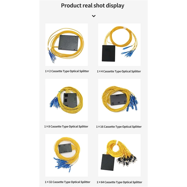
A PLC Splitter takes one optical signal and splits it into many outputs. This helps share signals in fiber optic networks. Pick the split ratio that matches what you need. Lower ratios work for fewer users. Choose the connector type like SC . PLC optical splitters (planar waveguide optical splitter) is a key component in optical fiber communication networks and is widely used in optical fiber distribution systems such as FTTH (fiber to the home) and PON (passive optical network). A fiber optic PLC splitter distributes a single optical signal into multiple outputs with high uniformity and low loss, making it ideal for. PLC splitter, also called Planar Waveguide Circuit splitter, is a device used to divide one or two light beams into multiple light beams uniformly or combine multiple light beams to one or two light beams. It is a passive optical device with many input and output terminals, especially applicable to. What Is a PLC Fiber Splitter? A PLC (Planar Lightwave Circuit) splitter is a passive optical device that evenly distributes optical signals into multiple output ports using silica waveguide technology. Choose the connector type like SC, LC, or FC. This. That's where PLC splitters come in. These compact passive components help service providers and network engineers distribute a single optical signal across multiple outputs without the need for power or complex configurations. If you're building or upgrading a fiber network and wondering what a PLC.
[PDF]

The maximum split ratio of the FBT splitter is as high as 1:32, which means that one or two inputs can be divided into outputs of up to 32 optical fibers. By dividing a single optical signal from a central Optical Line Terminal (OLT) into multiple outputs for Optical Network. In this guide, you'll learn how fiber splitters function in PON networks, the difference between PLC and FBT types, and how to choose the best model for your rollout in 2025. What Are Fiber Optic Splitters in PON? Fiber splitters are passive devices that divide one optical input signal into. FTTH relies on Passive Optical Network architecture, which enables one fiber leaving the central office to serve multiple subscribers through optical splitting. This structure eliminates the need for powered elements in the distribution segment, reducing operational costs while ensuring high. Optical splitter is an integrated waveguide optical power distribution device that serves to split optical signals. It is widely used in passive optical networks (such as EPON, GPON, BPON, FTTX, FTTH, etc. ) and plays an important role. When an optical signal is transmitted in a single-mode fiber. The FTTH network serves as the infrastructure enabling data transmission in the form of light signals over optical fiber from the operator's switching equipment directly to a home or business. Accurately understanding the principles, differences, and applicable boundaries of.
[PDF]
Use this beam splitters buying guide to compare major types, define selection criteria, and find suppliers: 🔬 Encyclopedia article: beam splitters 📦 Top-level product category: optical components and devices Click on a logo to get to the details of that supplier's offer. Also, please take a look at the list of 16 power splitter manufacturers and their company rankings. DATA PANEL CORPORATION. What Is a Power Splitter? What Is a Power Splitter? A power. Inmet and Weinschel brand Wilkinson & broadband resistive power dividers up to 40. 0 GHz with a variety of connector types, for dual channeled insertion loss measurements, calibration measurements, etc. 0 GHz with a variety of. Manufacturer of standard and custom power splitter combiners. Features include a female connector. Prototype and production volume runs are available. Suitable for defense electronics, ultra-broadband, commercial, and military space applications. Meets AS9100D standards. REACH and RoHS compliant. Narda-MITEQ's RF/Microwave Power Dividers and Combiners cover narrow and broad frequency ranges between DC and 44 GHz. Our products provide low insertion loss and VSWR. Our list of suppliers for. 5G splitter engineered for connectivity in URLLC, mMTC, and V2X deployments. Three hundred twenty-five RF microwave power divider, combiner, splitter models to choose from in 2way thru 64way configurations. RF splitters and.
[PDF]
The correct fix would be to land every neutral in its own terminal first, then combine EGCs as necessary to connect to the remaining holes. Example: join all #14s into one or two #14s, all #12's into one or two #12s, everything larger gets its own terminal. Exactamundo, with the same. Join ABR Electric's exclusive Residential Appliance Installer License (R. ) course in McKinney, TX, and elevate your career with expert-led training. Limited to just 5 spots, this course covers everything from NEC Codebook navigation to test-taking strategies, ensuring you're fully pre. more. A pigtail wire is a short cable used to lengthen short wires. Also, it can join several wires to become a single conductor for electrical connections. They also come in handy to lengthen circuit wires that are too short to reach a device. The National Electrical. How to Make Electrical Pigtails: This is a basic tutorial on what electrical pigtails are and how to make them. Disclaimer: Always use multiple sources and do your homework before performing any electrical work. Also, make sure all work is done within national and local code. As an electrician, I have to pigtail ground wires every once in a while and can say it's pretty easy once you get the hang of it. Below I will provide straightforward.
[PDF]
This updated list ranks the 20 largest fiber-optic cable companies worldwide and summarizes what each vendor is best known for—core product lines, regional strengths, and typical project fit. Use it as a fast shortlist when planning new FTTH/FTTA or data-center builds. With the global fiber optic cable market valued at $13. 92 billion and growing at 10. 46% annually, choosing from the best fiber optic manufacturers ensures your business infrastructure meets current demands and future scalability requirements. This comprehensive guide examines the top fiber optic. The global market for Fiber Optic Accessories was estimated to be worth US$ million in 2024 and is forecast to a readjusted size of US$ million by 2031 with a CAGR of %during the forecast period 2025-2031. 80% during the forecast period (2023-2032). This expansion is driven by surging demand for high-bandwidth networks, 5G. Corning Incorporated: A Top Fiber Optic Cable Maker in the USA Corning Incorporated, founded in 1851 and headquartered in Corning, NY, employs over 58,000 professionals and records annual sales exceeding $250 million. We note certifications.
[PDF]

In its most common form, a cube, a beam splitter is made from two triangular glass prisms which are glued together at their base using polyester, epoxy, or urethane-based adhesives. (Before these synthetic resins, natural ones were used, e. ). A beam splitter or beamsplitter is an optical device that splits a beam of light into a transmitted and a reflected beam. It is a crucial part of many optical experimental and measurement systems, such as interferometers, also finding widespread application in fibre optic telecommunications. In its. 📦 For purchasing, use the RP Photonics Buyer's Guide for beam splitters. It provides an expert-curated supplier directory, buyer-focused technical background information, and structured selection criteria to support professional procurement decisions. Light from an input fiber is first collimated, then sent through a beam splitting optic to divide it into two. The resultant output beams are then focused back into the output fibers. Note that jT j2 is the transmitted intensity. Similarly, E2 ! RE3 + T E4. The transformation matrix is then given by The elements of the beam splitter transformation matrix B are determined using the.
[PDF]

Attenuation describes the continuous loss along the fiber, while insertion loss describes the additional loss caused by components such as connectors, splices, or splitters. In fiber optic networks, particularly in FTTx (Fiber to the x) and PON (Passive Optical Networks) deployments, splitters play a central role in distributing the optical signal from a single source to multiple destinations. The split ratio and insertion loss are two key parameters defining their performance. A deeper understanding of these. This document describes how to calculate the maximum attenuation for an optical fiber. You can apply this methodology to all types of optical fibers in order to estimate the maximum distance that optical systems use. There are no specific requirements for this document. This document is not. By dividing a single optical signal from a central Optical Line Terminal (OLT) into multiple outputs for Optical Network Terminals (ONTs) at users' homes, splitters eliminate the need for dedicated fibers to each residence—slashing infrastructure costs while scaling network reach. Losses can be introduced by various means such as intrinsic material absorption, scattering, bending, connector loss and more. The tutorial has the following parts: When light propagates as a guided wave in a fiber core, it experiences some power losses. These are particularly important for long-haul data transmission through fiber-optic telecom.
[PDF]
The beam splitter is one of the important elements in optical waveguide circuits. To improve the performance of an optofluidic beam splitter, a microchannel including a two-stage main channel with divergent side walls and two pairs of inlet channels is proposed. Besides, the height of the inlets. M. Oulad Haddar; Improvement of optical characteristics of silicon based 1×3 beam splitter with photonic crystal waveguide. 20 January 2022; 2440 (1): 020001. 0075004 In this work, we propose a new structure of 1×3. In the second step of this work we propose an optimization of the conventional splitter design leading to suppression of the asymmetric splitting ratio to one-third of its initial value and to the improvement of the losses by nearly 2 dB. In addition, 50% size reduction of the designed structure. d for the power splitting ratios are vital for the adaptive optical networks and photonic computing. Conventional mechanisms such as thermo-optic, free-carrier, or mechanical tuning are usually volatile and require continuous p wer, limiting their suitability for low-frequency and low. Optical and Quantum Electronics This paper aims to study the design, simulation, and optimization of low-loss Y-branch passive optical splitters up to 64 output ports for telecommunication applications. For a waveguide channel profile, the standard material silica-on-silicon is used.
[PDF]

In this tutorial, we will show you how to fusion splice two fiber optic strands together in an easy 12 step process. The answer lies in splicing, both fusion and mechanical. Whether you're a professional technician or a DIY enthusiast, understanding the process of fusion splicing fiber optic cables is essential for maintaining high-speed communication networks. - Fiber Instrument Sales What is Fusion Splicing? How fiber optic splicers work, types, what they are used for. Steps to use this equipment and including how to test your fiber splice. The guide covers everything from basic principles of fusion splicing to detailed procedures; it is intended to provide both newbies and professionals with the necessary knowledge and skills. The operation and skills of fiber optic fusion splicing technology can be mainly divided into five steps: fiber stripping, fiber cutting, fiber melting, fiber sleeve, and fiber winding. And tools used for fiber fusion: fusion splicer; fiber cleaver; cable stripper; fiber optic stripper; alcohol;.
[PDF]
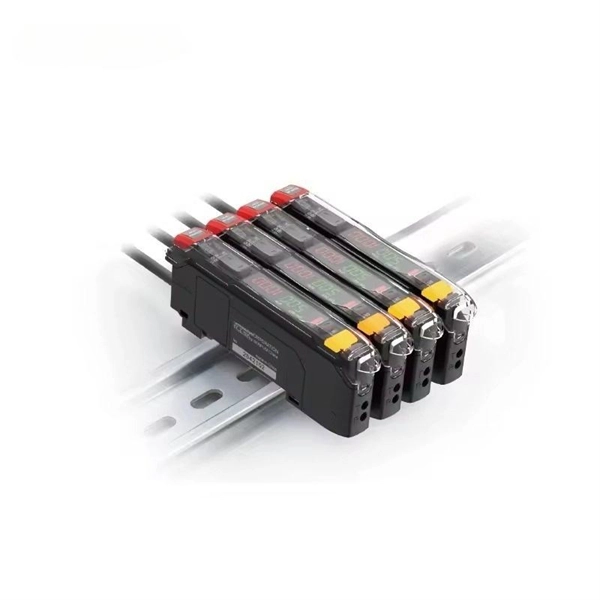
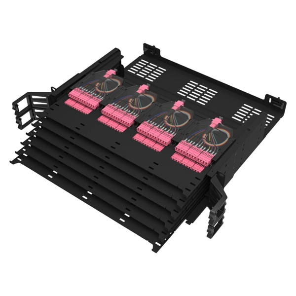
Corning closet connector housing (CCH) pigtail panels are CCH panels (CCH-CP) with factory-terminated and -tested pigtails installed. They accommodate all industry-standard connector adapter types including the LC, ST® compatible, SC, SC duplex, FC and MT-RJ, as well as the keyed. Optical module housing, also known as transceiver housing or optic module enclosure, is a protective casing designed to hold and protect optical modules used in various communication and networking applications. Depending on. NG4access ® Cabled Modules available in all module sizes and fiber counts up to 864 fibers NG4access ® Splice Tray Four sizes of interchangeable Propel fiber pass-through adapter packs provide the breadth of capabilities for virtually any configuration. Four sizes of interchangeable Propel fiber. To accompany all OCC fiber optic enclosures, Optical Cable Corporation developed snap-in fiber adapter plates that are versatile enough to meet any fiber application and durable enough to withstand field installations. All OCC fiber adapter plates guarantee performance parameters for the. Adobe Reader is required to open the pdf files above. Click here to download a free copy. Consolidate your fiber optic connections in industrial environments with our DIN rail patch panel, with a modular design and tool-free installation save space and simplify deployment.
[PDF]
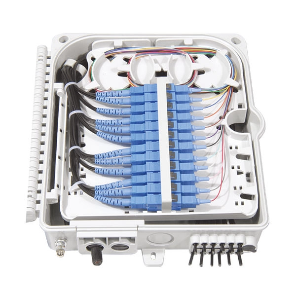
When selecting the right fiber optic splice tray, prioritize compatibility with your cable type, secure fiber management, and ease of installation. Corning splice trays offer an easy way to store fiber optic cables and splices while protecting them from damage during fusion and mechanical splicing. The trays are engineered to use with both loose tube and tight-buffered optical cables. Their generous size and craft-friendly design help prevent. Fibre optic splicing trays are an essential part of manipulating and ordering optical fibers inside a network structure. Since the need for higher data rates and effective communication gets more robust, the utilization of optical fibers has become increasingly widespread across multiple spheres of. Optical / fiber optic 12 or 24 fiber splice tray for holding spliced fibers of fiber optic cable. For most network installations—especially in data centers or FTTH (Fiber-to-the-Home) deployments—a modular, stackable splice tray with 12 to 24 port. Discover CommScope fiber splice trays, fiber optic splice trays, and a convenient fiber splice organizer. Organize fiber connections with ease. Because optical fibers are sensitive to pulling, bending, and crushing forces, use fiber splice trays to provide secure routing and an easy-to-manage environment for fragile fiber splices. In the past, fiber optic splice trays were usually installed in a box that hung on the wall.
[PDF]
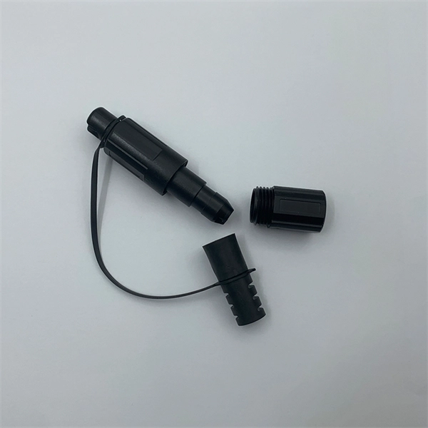
According to different types of pigtail cable connector terminated at the end, there are LC fiber pigtail, SC pigtail, ST pigtail, FC pigtail, fiber pigtail and so on. With different structures and appearance, each of them has their own advantages in diffe. According to different types of pigtail cable connector terminated at the end, there are LC fiber pigtail, SC pigtail, ST pigtail, FC pigtail, fiber pigtail and so on. With different structures and appearance, each of them has their own advantages in different applications and systems. Let's go through some widely used ones. SC Pigtail: SC pigtail. Fiber Optic Pigtails, In fiber optic cable installation, how cables are attached to the system is vital to the success of network. If done properly, optical signals would pass through the link with low attenuation and little return loss. pigtail offers an optimal way to joint optical fiber, which is used in 99% of single-mode applications. This pos. pigtails can be divided into single-mode (colored yellow) and multimode (colored orange) fiber. Multimode pigtails use 62.5/125 micron or 50/125 micron bulk multimode fiber cables and terminated them with multimode fiber optic connectors at one end. 10G multimode fiber cables (OM3 or OM4) are also available in optic pigtails. The jacket color of 10.
[PDF]
The diffractive beam splitter is used with monochromatic light such as a laser beam, and is designed for a specific wavelength and angle of separation between output beams.OverviewA beam splitter or beamsplitter is an that splits a beam of into a transmitted and a reflected beam. It is a crucial part of many optical experimental and measurement systems, such as. In its most common form, a cube, a beam splitter is made from two triangular glass which are glued together at their base using polyester,, or urethane-based adhesives. (Before these synthetic,. Beam splitters are sometimes used to recombine beams of light, as in a. In this case there are two incoming beams, and potentially two outgoing beams. But the amplitudes.
[PDF]
Dichroic Mirror split light or beam based on their wavelength (or color). example : transmit red light and reflect green light. Additionally, beamsplitters can be used in reverse to combine two different beams into a single one. Beamsplitters are often classified according to their construction: cube or plate. A beam splitter or beamsplitter is an optical device that splits a beam of light into a transmitted and a reflected beam. It is a crucial part of many optical experimental and measurement systems, such as interferometers, also finding widespread application in fibre optic telecommunications. In its. 📦 For purchasing, use the RP Photonics Buyer's Guide for beam splitters. It provides an expert-curated supplier directory, buyer-focused technical background information, and structured selection criteria to support professional procurement decisions. What are Beam Splitters? A beam splitter (or. The beam splitter splits and then recombines infrared radiation, while the detector picks up the resulting signal. It's sensitive to both intensity and frequency. Together, they decide just how accurately an instrument captures those unique infrared “fingerprints” from different substances. A beam. These optical components divide incident light into two distinct beams: one reflected and one transmitted. This precise ability to direct light paths makes beam splitters essential in various applications, including imaging systems, laser systems, and telecommunications.
[PDF]