
How to install a fiber optic cable into a patch panel. Fibre Optic Patch Panel Installation Fibre Optic Cabling Know How - how to connect Fibre Optic Cable to a Patch Panel This video shows you how to install. Fiber optic patch panel is a crucial component in optical communications networks. It also known as a fiber patch panel or fiber distribution panel. It serves as a central point for organizing, managing, and connecting fiber optic cables. At its core, a fiber optic patch panel acts as a hub for. What are the best practices for fiber patch panel installation? The best practices below help to avoid installation issues and ensure ease of service for the system. Penetrate the enclosure from the side or bottom to minimize the risk of water intrusion. Step 1: Gather the Tools and Equipment The first step in connecting. How to Install a Fibre Optic Cable into a Patch Panel ( Fibre Optic Patch Panel ) How to install a fiber optic cable into a patch panel. This is essential for streamlining network. Running fiber internally involves extending this high-speed link from the service entry point to a centralized location, such as a dedicated media closet or network rack. This DIY effort is undertaken to maximize performance, improve aesthetics, or relocate the Optical Network Terminal (ONT) to a.
[PDF]
A patch panel is a passive hardware unit that consolidates multiple network connections in one location. Typically rack-mounted, it features ports on the front for easy access and termination points at the back for permanent cabling. From the outside, network planning can look like “run cables, place a switch, get the internet working. By linking wall outlets or devices to network switches through. Ever opened a server room and felt like you walked into a jungle of tangled cables? You're not alone. Businesses of all sizes wrestle with messy wiring, slow troubleshooting, and inconsistent connectivity. But here's the thing: it doesn't have to be that way. The unsung hero behind neat, efficient. We manufacture globally recognized cable management systems and tools designed for your network racks. Explore our product brochure, NIS2 whitepaper, and much more. designed to u2028help you understand our solutions and make informed decisions. Discover who we are and how we're shaping the future. Enter the dynamic duo of **patch panels and racks**: your knights in shining armour against cable clutter. Imagine them as multi-port outlets, neatly organising incoming and outgoing. A fiber patch panel is a mounted enclosure—either rack-mounted or wall-mounted—used to terminate, manage, and interconnect multiple fiber optic cables. It acts as a hub for organizing splices and patch cords, streamlining fiber management and preserving signal integrity. Cable Organization:.
[PDF]
Browse different network patch panel icons in unique different design styles. Patch panels are one of the best ways to manage an expansive local area network (LAN) by providing quick and easy access to the ports and connections that connect them altogether. They come in a range of sizes, and are typically mountable, whether that's on a wall, or on a rack to make for easier. Browse 10000 different network patch panel icons in 151 unique design styles. Download network patch panel icons. ICC's patch panel color icons were created to provide an easy color identification system specially designed for our cross-connect patch panels. They are available in nine colors. ITEM NUMBER DESCRIPTION ICMPPSCIxx* VOICE icons and DATA icons 6 pcs. ICMPPICVxx*. Icons (33) Photos. Find 33 Network Patch Panel images and millions more royalty free PNG & vector images from the world's most diverse collection of free icons. Get free icons of 48 patch panel in style for your design. You're also welcome to check new icons and popular. design styles for web or mobile (iOS and Android) design, marketing, or developer projects. These royalty-free high-quality Patch Panel Icons are available in SVG, PNG, EPS, ICO, ICNS, AI, or PDF and are available as individual or icon packs. You can also customize them to match your brand and.
[PDF]
They come in a range of sizes, and are typically mountable, whether that's on a wall, or on a rack to make for easier cable and port management. Patch panels are a great way to improve your network management by making it simple to organize your cables and connections. In this case, we will be talking about a very versatile type of patch panel known as a shielded wall mounted patch panel. Patch panels even let you. When building or upgrading a fiber network, choosing between rack-mount and wall-mount patch panels can have a big impact on performance, organization, and scalability. The difference lies in where and how they fit into your setup. Check each product page for other buying options. Need help? Streamline your cabling with wall-mounted patch panels. Discover compact, space-saving options featuring sturdy metal construction and flexible installation. Among the various FDU types—including fiber distribution boxes, termination units, rackmount patch panels, and outdoor-rated enclosures—wall mount fiber patch panels stand out for their space-efficient design and versatile applications. Whether you're setting up a home office network, a small data. Pick wall mount patch panels for small networks. They are more organized and can expand easily.
[PDF]

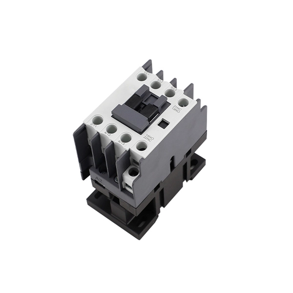
There are many types of protective relays, and each one is designed for a specific type of protection. Common types include overcurrent relay, differential relay, distance relay, earth fault relay, and under/over voltage relay. Protective Relay Definition: A protective relay is an automatic device that senses abnormal conditions in electrical circuits and triggers actions to isolate faults. HT panel protection relay. The HT power supply is received from GO switch and distributed to the. Provides protection, logic, and metering All-in-one solution. Combines protection, sensors, control power, and circuit breaker in a single package Typically added to a breaker close circuit to prevent accidental reclosure after a trip. Three fundamental components required for each circuit breaker. Its main purpose is to safeguard electrical equipment like transformers, generators, and transmission lines from damage due to. There are different types of relays available and each type is used based on the requirement. So this article discusses an overview of a protective relay or protection relay – working with applications.
[PDF]

The K factor (or zero-sequence compensation factor) adjusts the measured impedance for the phase-to-ground fault loop by accounting for the contribution of zero-sequence currents. This compensation is critical because zero-sequence current introduces an offset in the fault impedance. The following Terms are used in protective relaying: 1. Fault Clearing Time 5. Drop Out or Reset value 8. Sealing Relay or holding Relay 10. Hermetically sealed, corrosion resistant metal can. Detail specifications and ordering data appear on the Data Sheet below. NewElec's KA, KB & KC Series relays provide robust and dependable motor protection relays designed to safeguard critical motors in a wide range of industrial applications. Fixed thermal curves (Class 15 Cold - Class 5 Hot) with thermal pre-loading, match the Hot and Cold stall times of the motor during operation. The KA relay is mains powered. The protection and control devices in electrical equipment can be referred to by numbers, with appropriate suffix letters when necessary, according to the functions they perform. These numbers are based on a system that is adopted by a standard for automatic switchgear by Institute of Electrical.
[PDF]

The modern electric power transmission, control, and distribution network demands precision, reliability, and advanced data analytics for each step in its operation. As a Relay Protection Engineer, your work in relay testing and commissioning is critical to ensuring system safety and continuity. In. The testing and verification of protection devices and arrangements introduces a number of issues. This happens because the main function of protection devices is related to operation under fault conditions so these devices cannot be tested under normal operating conditions. Protection relays are critical for detecting faults, initiating protective actions, and isolating faulty sections of the. Relay systems protect high-voltage equipment and transmission lines to ensure safe, stable systems. Although failure of a protective relay system may have severe local or regional impacts, most protective relay systems are not required to operate to prove they are in working order. Ensuring that. The strategies available to remove these risks are many, but all involve some kind of testing at site. Modern power systems are becoming increasingly complex, with growing demand, integration of renewable energy, and rising expectations for reliability and safety. In this environment, protection relays serve as the guardians of.
[PDF]
Microprocessor-based solid-state digital protection relays now emulate the original devices, as well as providing types of protection and supervision impractical with electromechanical relays.OverviewIn, a protective relay is a device designed to trip a when a is detected. The first protective relays were electromagnetic devices, relying on coils operating on moving par. Electromechanical protective relays operate by either, or. Unlike switching type electromechanical with fixed and usually ill-defined operating voltage thresholds. Electromechanical relays can be classified into several different types as follows: "Armature"-type relays have a pivoted lever supported on a hinge or knife-edge pivot, which carries a moving contact. These relays may.
[PDF]
Pilot-wire relaying is an adaptation of the principle of differential relaying to line protection and functions to provide high-speed clearing of the line for faults anywhere on the line. Pilots include wire pilot (us.
[PDF]
The optical fiber cable and the cable are the same, the difference is located in the fiber patch cord without the network shielding layer, and the center is the optical fiber glass core. The glass envelope surrounds the core, followed by a thin plastic jacket on the outside. The main components of. Of the more than a dozen types of fibre-optic connectors available, the four most commonly used today are LC, SC, FC, and ST. In addition to serving the same general function, the four connectors differ in size, locking mechanism, and best applications. The following guide systematically describes. A fiber optic connector is a mechanical device that allows two fibers to be joined precisely, enabling light to pass with minimal insertion loss and reflection. A good connector: Provides low insertion loss (minimal signal attenuation). They directly affect insertion loss, return loss, reliability, and long-term network stability. The ferrule diameter of the SC connector is 2. There is a spring inside the flange and if you hear the springs twanged when you insert the connector into the flange, that means the. Whether back in the late 1990s or today, you will see 8P8C RJ45 type connectors at the end of Ethernet patch cords and keystone jacks mounted in walls running back to patch panels. The T568A and T568B color code has remained the same too, dictating the wiring color code sequence to make proper.
[PDF]
Single mode fiber patch cord: Single mode 9/125um optic patch cord are designed for long-distance transmission. They have a smaller core diameter (typically 9 microns) compared to multimodeoptic.
[PDF]

A Mode Conditioning Patch Cord (MCPC) is a specialized fiber patch cord designed to control the launch condition of light from a single-mode transmitter into a multimode fiber. Fiber optic cables primarily come in two types: Multimode Fiber (MMF): Has a larger core, allowing multiple light modes (paths) to travel. It's designed for short-distance, high-bandwidth applications within buildings or campuses. Common types are OM1, OM2, OM3, and OM4. Its primary purpose is to reduce differential mode delay (DMD) and prevent bandwidth limitation when legacy multimode. FS offers OM1 & OM2 mode conditioning fiber optic patch cables (MCP) in any connector & cable length, optimal for eliminating differential mode delay effects. This document describes the installation and use of the mode-conditioning patch cords listed in Table 1. 3z-compliant optical fiber assembly consisting of a single-mode fiber permanently coupled off-center to a 62. 5/125) fiber optic cable by offsetting the Singlemode Laser launch from the.
[PDF]

Learn how to identify and prevent these common issues. Installing a fiber optic patch panel may seem straightforward, but many network issues originate from small installation mistakes. Poor fiber routing, incorrect bend radius, or improper labeling can all lead to signal loss, maintenance difficulties, and unexpected downtime. This article highlights. What Can Go Wrong with Copper Patch Panels? What Can Go Wrong with Copper Patch Panels? Are you aware of the problems that a copper patch panel can cause in your network infrastructure? Learn how to identify and prevent these common issues. However, installation errors can lead to issues that impact network performance. This article offers guidance on proper installation and troubleshooting. Network patch panel, cable manager, network cable, wire stripper, crimping tool, zip ties. Use a small yellow tool or wire stripper to remove the outer jacket of the network cable. Cut off the cross-shaped skeleton of the Cat6 patch cord. Insert. Our guide delivers actionable, step-by-step best practices for rack layout, cable management, and patch panel installation. Many seasoned pros (and plenty of first-timers) run into avoidable pitfalls that turn a simple installation into a costly headache.
[PDF]
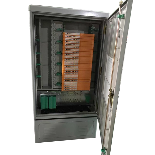
Fiber optic patch panels are enclosures that act as a distribution hub for fiber cable. A bulk (multi-strand) fiber cable enters the patch panel and then each fiber strand is separated into individual strands or pairs of strands. Fiber optic communications has been a rapidly expanding industry for the last 20 years. In its early years, it was mainly used for backhaul communications between large ISP's. But now fiber is widely used and can be found almost anywhere. It's probably in your ofice, on the telephone poles outside. A fiber patch panel is a mounted enclosure—either rack-mounted or wall-mounted—used to terminate, manage, and interconnect multiple fiber optic cables. It acts as a hub for organizing splices and patch cords, streamlining fiber management and preserving signal integrity. It provides a central point where incoming fiber cables can be connected to outgoing patch cords, making the network structured, accessible, and easy to maintain. This makes it easier to alter or troubleshoot the connections as they act as a central point where. Fiber patch panels play an increasingly important role in the optical fiber network due to the widespread use of high-density cabling systems in data centers. They are available in various fiber connector types, such as LC patch panel, SC patch panel and MTP patch panel. This article explores the structure, functionality, types, and benefits of fiber optic patch panels. What's the Fiber Optic Patch.
[PDF]

Excavate the cable at the break point and use a fiber optic cutter to remove the damaged section. Use a high-precision fiber cleaver to prepare the fiber ends for splicing. Step1 : Identify the optical cabinet and network operating center, and find the fiber optic splitter. Step 2: Identify the splitter number. Step 4: Find the optical fiber port and cable sequence that leads to the user. 2) The. Here are the steps to patch a fiber cable. Make sure the connectors are free from dust or dirt and that there is no damage to the cable's. When fiber cables sustain damage, specialized repair techniques help restore connectivity and maintain data integrity. This comprehensive guide outlines professional fiber optic repair protocols that align with industry best practices. Adhering to precise methodologies, we can mend impaired cables. Learn how to splice fiber optic cable step by step in this complete guide! In this video, you'll see the full fiber splicing process — from fiber preparation, cleaving, and fusion splicing to final testing. Whether you're a network technician, IT professional, or telecom operator, you'll find practical steps, tools, and tips to restore. By understanding these key elements and following the outlined steps, you can effectively repair fiber optic cables and maintain the high-performance network necessary for today's demanding communication needs. When it comes to ensuring nice network experiences for users, the condition of a fiber.
[PDF]


