These two categories define how light travels through the fiber core: Transmits a single light mode; very low attenuation; supports long-distance transmission up to 100 km or more. Transmits multiple light modes; higher dispersion; best for shorter distances. The most common distinction is between single mode vs multi mode fiber optic cable. There are many classifications of optical cables, due to the installation environment. It has stronger pressure resistance, corrosion resistance, greater tensile. In the landscape of network infrastructure, three primary cable categories dominate connectivity: twisted-pair copper cables, coaxial cables, and fiber optic cables. While copper-based solutions (such as Cat5e/Cat6 for twisted pair or RG-6 for coaxial) have long served as workhorses for local and. We'll cover single mode, multimode, and armored fiber cables below. Single mode fiber optic cable is made up of a small diameter glass or plastic core surrounded by cladding, which is a layer of reflective material. This small diameter core, typically around 9 microns in diameter, allows only one. There are two main types of fiber optic cables: single mode and multimode. Although they can do the same job in some instances, the different construction methods make each of them better suited to certain tasks and budgets.
[PDF]
Fiber testing is the process of verifying the performance of optical fiber cabling. This process includes a range of tests and measurements such as insertion loss, optical return loss, and fiber length. It encompass.
[PDF]
It emphasizes the importance of considering mechanical and environmental aspects, referring to the IEC 60794-2 series for technical specifications. The document details the characteristics of optical fibers and cables, including transmission, microbending and macrobending. Nowadays, optical communications are the most requested and preferred telecommunication technology, due to its large bandwidth and low propagation attenuation, when compared with the electric transmission lines. Besides these advantages, the use of optical fibers often represents for the telecom. As environments are becoming increasingly harsh, the ability of optical fiber cable to withstand such environments is of the utmost importance to outside plant users. Laboratory accelerated aging environments have long been used as a measure to predict field performance of optical fiber and cables'. This study investigates the strain transfer mechanism for different types of fiber optic cables while embedded in concrete cubes, sustaining a boundary condition which features a displacement discontinuity. The strain transfer mechanisms for different cables are compared under increasing strain. This document outlines the recommendations for single-mode optical fiber cables used in telecommunication networks within buildings, focusing on their mechanical and environmental characteristics. It specifies that these cables must comply with standards such as ITU-T G.
[PDF]

While traditional fiber optic cables contain individual fibers encased in a protective jacket, ribbon fiber cables organize fiber optic strands in a flat ribbon structure, creating freedom with space conservation and cable management. Data Centers: The flexible ribbon cables deliver phenomenal bandwidth between densely packed servers and networking gear in data centers. Motor Meter: Ribbon cables can be used to connect the control circuitry to the display or to the motor drivers. Telecom Devices: In telecommunications, flat. Ribbon cables offer higher fiber counts and greater fiber density than any other cable construction designed for the outside plant (OSP), four times the highest-fiber-count loose tube cable. Ribbon cables also enable mass-fusion splicing, whereby each 12-fiber ribbon can be spliced in a single. The technology of ribbon fiber optic cables is well-established in the telecommunications industry and is favored for its high fiber density and compact size. Join us as we embark on a journey of discovery, demystifying the technology that has changed the way we connect and communicate. Welcome to the world of Ribbon Fiber Optic Cables. One of our most innovative technologies is the ribbon fiber optic cable —a compact, powerful solution that is transforming the way organizations manage high-density connections while optimizing valuable space. In this article, we'll delve into why ribbon fiber optic cables are a game-changer, how.
[PDF]

Fiber optic loss calculation formula: Total link loss (LL) = Cable attenuation + Connector attenuation + Fusion attenuation [Note: If there are other components (such as attenuators), their attenuation values can be added]. Intrinsic Optical Fiber Losses comprise of absorption loss, dispersion loss and scattering loss caused by the structural defects. The detailed information about these optical losses and how to reduce them are. Calculate fiber optic signal loss based on cable length, attenuation, and connector losses. Determine cable loss, connector loss, and total system loss in decibels (dB) to assess signal quality and repeater requirements. Fiber optic loss is calculated in two parts: cable loss and connector loss. This calculator determines fiber loss based on input power, output power, and the length of the fiber optic cable. In summary, fiber optic loss is. Use this worksheet to input values for all variables that will impact your system's performance. After entering your values, please ensure you click the 'Calculate Link Loss' button at the bottom of the page to generate your total link loss. This step is necessary to see if your system falls within. Optical fiber loss is a term for signal loss affecting transmission reliability. Optical fiber loss is.
[PDF]

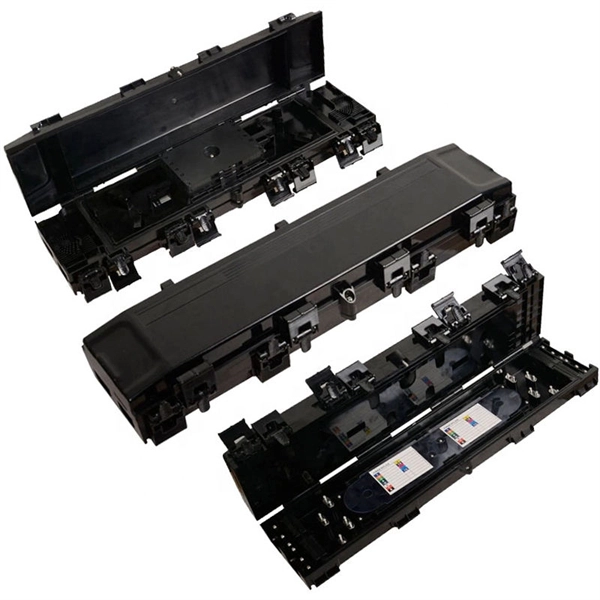
Fusion splicing is the process of fusing or welding two fibers together usually by an electric arc. Fusion splicing is the most widely used method of splicing as it provides for the lowest loss and least reflectance, as well as providing the strongest and most reliable joint between. This guide reveals the secrets to fusion splicing with little fluff—just proven, straightforward techniques refined from years of work in the field. The goal is to fuse the two fibers together in such a way that light passing through the fibers is not scattered or reflected back by the splice, and so that the splice and the region surrounding it are almost as strong as the. A fusion splicer is a specialized tool used in fiber optic networks to join two fiber optic cables together permanently. This process creates a strong and reliable connection that can withstand. Splicing fiber optic cable is an extremely important phase for making dependable, high-speed communication infrastructures. Fusion splicing stands out as a superior technique for joining optical fibers, offering a seamless, low-loss connection that is crucial for reliable fiber optic networks. Let's explore the fundamentals of mechanical and fusion.
[PDF]

Optical connectors are the physical interface that links an optical device to a fiber optic cable. Fiber optics are used in many applications, including medical imaging, automotive, military, industrial, and commercial (e., telecommunications). Each of these. Many people ask the same question: Can you use a fiber optic cable with an RJ45 port? The short answer is no - RJ45 connectors are designed for electrical Ethernet signals, while fiber optics transmit light pulses through glass or plastic. However, modern networks often combine both technologies. An optical fiber connector is a device used to link optical fibers, facilitating the efficient transmission of light signals. An optical fiber connector enables quicker connection and disconnection than splicing. They come in various types like SC, LC, ST, and MTP, each designed for specific. Proper connection of fiber optic cables is essential to harness these benefits fully, as even minor errors can lead to significant performance issues like signal loss. This article will guide you through the necessary tools, materials, and methods on how to connect fiber optic cables effectively. Most SFP fiber optic modules use LC connectors, while SC connectors are mainly found in legacy networks and MPO/MTP connectors are used for high-density cabling rather than directly on standard SFP modules. FC FO LC connectors for fiber optic.
[PDF]
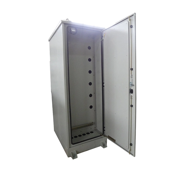
The process involves a combination of national infrastructure, local engineering, and property-level setup. In this guide, we'll break down the fiber installation process from start to finish and explain key components such as fiber cabinets, flower pods, ducting, and ONT setup. That's the kind of experience fiber-optic internet makes possible. Fiber optic internet is. Professional fiber optic installation companies ensure your network infrastructure meets current demands while supporting future growth through expert design, installation, and testing services. 85% of fiber network failures trace back to contaminated connectors—professional installation with. In the spirit of self-reliance and technical mastery, we've crafted this detailed guide to empower you to take control of your own network by installing fiber optic cables yourself. Our company specializes in high speed Ethernet, fiber optic, and any other medium of low voltage wiring. Our voice, data, audio, and video cabling installations and products are all top quality! We are an established. Your trusted source for structured voice & data cabling. We provide expert installation and maintenance for all your business communication needs in San Jose and surrounding areas. We offer San Jose and surrounding areas a one source solution for all your data cabling & business phone system needs.
[PDF]
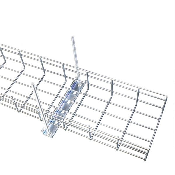
Outdoor optical cables generally consist of bare fibers, loose tube, water-blocking materials, strengthening elements, and outer sheath. They come in various structures such as central tube design, layer stranding, and skeleton structure. An outdoor optical cable is a type of optical fiber cable used for communication transmission. It features an additional protective layer known as armor or metal sheathing, which provides physical protection to the optical fibers, making them more durable and capable of operating in harsh. Outdoor fiber optic cables transport data and communications signals over long distances while enduring extreme environments. As the backbone of modern telecom infrastructure, these cables come in specialized designs to operate reliably despite the challenges of humidity, tension, wind, rodents. Fiber optic cables are made of materials that allow light to travel through them. They carry a lot of data very quickly on fiber strands which are the width of a human hair! But are you wondering what materials fiber optic cables are made of? The most common materials are glass and plastic. This. Fiber optic cables are designed to provide high-speed, no-signal-loss, and EMI-free communication in telecommunication, powergrid, datacenter, broadband, and industrial applications. Rugged fiber optic cable is constructed so as to resist ultra-violet light and temperature fluctuations and may include features to.
[PDF]

Optical transmission windows are specific wavelength ranges where light travels through fiber with minimal attenuation (signal loss) and dispersion (distortion). These low-loss windows are essential for maintaining the performance and reach of fiber optic communication systems. Fiber optic cable is a type of cabling that contains one or more optical fibers for transmitting data at high speeds and/or over long distances using light. These fibers are most commonly made of glass and are very thin, typically less than a tenth of the width of a human hair. Fiber optic cable. This is your "QuickStart" guide to testing fiber optic cable plants, patchcords and communications equipment with a fiber optic light source and power meter. We'll give you the basic information you need and provide some printable references. Optical power, required for measuring source power, receiver power and, when used with a test source, loss or attenuation, is the most. Fiber optic loss testing is an essential part of maintaining reliable, high-performance fiber optic networks because it helps identify potential issues and ensures that the system meets the required performance specifications. In this blog, we'll explore what a power meter and light source are and. This part of IEC 61280 is applicable to the measurement of attenuation of installed optical fibre cabling plant using multimode optical fibre.
[PDF]

The basic structure of optical fiber consists of three primary components: the core, the cladding, and the buffer coating. The core is the central part of the optical fiber through which light is transmitted. An optical fiber cable is a complex structure designed to protect fragile glass fibers that transmit digital data using light signals. This advanced cabling solution allows fast, secure data transfer and telecom over long distances. Understanding the components within a fiber optic cable enables. In this blog, we will delve into the fundamental components and structure of optical fiber to gain a better understanding of this revolutionary technology. At its core, optical fiber is a thin, flexible, and transparent fiber made of glass or plastic, which serves as a medium for transmitting light. They consist of three main components and are available in several structures suited to different uses. In this article, discover in detail these components and the various structures of fiber optic cables. The core: made of silica, molten quartz, or plastic, in which optical waves propagate. Dielectric material conducts.
[PDF]
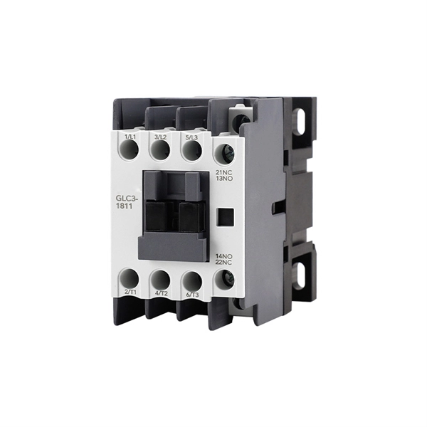
Metal conductors in cables serve to conduct electricity, while optical cables use optical fibers to transmit light signals, and optical fibers are thin, flexible media that transmit light beams, forming the core part of optical cables. Let's take a closer look at. Yes, there can be differences between optical cables in terms of their construction materials, connector types, and the quality of the glass fibers used. These factors can affect the cable's ability to transmit data effectively over long distances and at high speeds. It's important to choose the. Toslink—short for “Toshiba Link”—is a very specific subset of fiber‑optic technology created in 1983 to move consumer‑level digital audio from one box to another. Let's take a closer look at these differences. Cables physically connect these devices, enabling them to communicate within a network. In computer networking, it is very important to know the distinctions between the different. These cables are used mainly for digital audio connections between devices. A fiber-optic cable, also known as an optical-fiber cable, is an assembly similar to an electrical cable but containing one or more optical fibers that are used to carry light. They are mainly used in telecommunications, data transmission and consumer electronics. Compared to traditional cables that carry electrical signals, optical ones have Cables some advantages.
[PDF]

This article will provide an in-depth analysis of outdoor cable types, key selection criteria, core installation steps, critical precautions, as well as subsequent testing and maintenance guidelines, helping you build a robust and durable outdoor optical communication link. Therefore, understanding the characteristics of outdoor fiber optic cables and mastering proper installation methods is crucial. Plan your outdoor fiber installation carefully by surveying the site, choosing the right cable type, and following FOA and OSP standards to ensure reliability. In this video, we'll walk you through the process of establishing a robust outdoor fiber connectivity solution. Follow our guide and establish a r. more Welcome to. Running a cable through an exterior wall can be a daunting task for many homeowners, but with the right tools and techniques, it can be done efficiently and safely. With the increasing demand for high-speed internet and reliable networking, it's essential to know how to properly install CAT 6 cables outdoors. In this article, we'll take you.
[PDF]

Mechanical splicing is a fast way to join two fiber optic cables. Instead, you line up the fibers inside a small holder made of plastic or metal. The holder keeps the fibers steady. A special gel helps light move through the joint. In this guide, we'll walk you through exactly how to splice fiber without a fusion splicer, covering the tools you need, the step-by-step process, performance specs, and common mistakes to avoid. By the end, you'll be equipped to make clean, low-loss connections in any field scenario. Experts who add quality contributions will have a chance to be featured. Learn more Mechanical splicing is a. Executive Summary: A fiber optic pigtail is one of the most commonly specified yet least understood components in structured cabling. Get the wrong connector type, the wrong polish, or skip proper fusion splicing technique—and you're looking at elevated signal loss, increased back reflection, and a. Fiber optic cable splicing connects two cables, creating a strong link for fast data transmission. Fusion splicing uses heat to join fibers, while mechanical splicing aligns fibers without the need. This video will show you how to repair a damaged fiber optic cable strand without a fusion splicer. This temporary fix will get your network back up and running, giving you time to source new fiber cable. Fusion Splicing Fusion.
[PDF]

What is the main cause of attenuation in fiber? Attenuation in fiber mostly happens from absorption and scattering. The fiber material takes in some light as it moves. Both of these things make the signal weaker as it goes through the. Optical Signal Attenuation is the single greatest factor limiting the distance and performance of your network. Understanding it is crucial for anyone involved in data centers, telecommunications, or enterprise networking. This guide will demystify signal loss, explore its causes, and show you how. Optical fibers are a key component in modern communication systems, carrying signals over long distances. However, even the most advanced optical fiber suffers from attenuation, which is the loss of signal power as it travels along the fiber. Understanding the causes of signal loss and implementing mitigation strategies is essential for maintaining network efficiency. From infrastructure planners to telecom engineers. Optical fiber technology enables rapid data transmission over vast distances by guiding light signals through thin strands of glass. Losses can be introduced by various means such as intrinsic material absorption, scattering, bending, connector loss and more.
[PDF]
