Lighting Control System | Smart Lighting Wiring Setup | Full Guide In this video, you will learn how to connect and install a Lighting Control System step-by-step. This guide covers wiring setup, switch modules, dimming control, sensor setup and panel . as a guide for proper and reliable installation. The mounting location should e selected and prepared based on the application. All electrical wiring and mounting hardware (i. ) should be prepared with consideration of the requirements o cuit breaker before. Intelligent Lighting Controls' installation guides provide detailed instructions on how to install all of our solutions. The Lightolier Controls Optio Lighting Control Panels are high-performance, wall mounted lighting control panels which offer a wide range of dimming and relay modules to accommodate any lighting control application.
[PDF]

A wiring diagram for a photocell and timeclock controller provides a step-by-step guide for installing and connecting all the components in a light system. It shows exactly how each component fits into the overall scheme of things, as well as what wires to use and which connections to. Intelligent Lighting Controls' wiring diagrams show detailed schematics of our solutions. A lighting control module is the “control center” for your lighting system. It acts as a bridge between your physical lighting fixtures and the smart systems that manage them. Instead of relying solely on traditional wall switches, you can control your lights via remotes, mobile or web apps. This guide will discuss the steps needed to integrate with URC Total Control. Commission CSI Controllers Step 2. Locate/Download latest TCM files/Module Step 3. Network Setup Step 6. Supports DALI V2 compatible switches and sensors, works out of the box. Simple and easy setup. ControlByWeb® IoT controllers are a great fit for lighting control in edge applications. Understanding the components that make up a modern lighting system, and how they relate to one another is key to ensuring the best performance and.
[PDF]
Follow these steps to configure DHCP server or relay on a switch. The VLAN for which DHCP server will be configured on switch is assigned to the ports connecting to the DHCP clients. You can do this by applying a relevant port profile to the port. Hi all, Have a Unifi USW Pro that I want to use as my core switch. Running into a DHCP relay issue where I have a windows server with 2 DHCP scopes, one for default vlan traffic one for BYOD devices. I want the switch to do the routing so that if an SSID is tagged a vlan X, the switch with ip. I'm trying to obtain a DHCP IP for the client directly connected to the Branch Office Core switch. I can ping the DHCP Server IP from the branch office core switch. For more information about port profiles, see. A DHCP relay forwards DHCP packets between the DHCP server and clients. When the DHCP server and clients belong to different network segment, the DHCP relay needs to be configured. The DHCP. Hello All, Attached guide provides in-depth understanding about DHCP Server and DHCP Relay Implementation. Hi Priyank, thank you for the complete information. I have DHCP configured on a linux server and the core switch which has layer 3. -Vlans are created and access ports are configured with the respective vlans on the access switches. -used network command -used default-router command which.
[PDF]

Average Optical Power: How bright the light is (measured in dBm). Too dim? Your signal gets lost in the fiber. Extinction Ratio: The difference between “on” (1) and “off” (0) light power. A higher ratio = cleaner signals. Transmitter Side: An electrical signal hits a laser diode (LD) or LED, which spits out light. Receiver Side: Light enters a photodetector (like a tiny solar cell), which turns it back into electricity. A built-in amplifier boosts the signal for your. The average transmitted optical power refers to the optical power output by the light source at the transmitting end of the optical module under normal working conditions, which can be understood as the intensity of light. In communication, we usually use dBm to represent optical power. However, in practical use, we adopt the average Tx power. The transmission power is related to the. This article provides an in-depth analysis of two key performance indicators of optical modules: transmitter power and receiver sensitivity. Transmitter power characterizes the average optical power output from the laser under rated conditions, while receiver sensitivity indicates the minimum. An optical module is a connecting module that serves as an optical-electrical conversion device. At the receiver end, the optical signals are reconverted into electrical.
[PDF]

Continuous-wave operation (cw operation): The laser is continuously pumped and emits light continuously, either on a single resonator mode (→ single-frequency operation) or on multiple modes (see also: single-mode operation). How do optical. EML stands for Externally Modulated Laser (corrected from "External Modulated Laser"). Its basic principle is to supply a constant current to the laser diode, ensuring the LD emits continuous, stable light. An external electro-absorption modulator (EAM) then adjusts light transmittance to generate. A wavelength swept light source emits laser light with a continuously sweeping wavelength. It is suitable for shape measurement and displacement measurement utilizing OFDR (Optical Frequency Domain Reflectometry), an optical sensing method using the coherence of laser light. The transmitting interface inputs electrical signals of a certain bit rate, which are then processed by internal driver chips. Subsequently, the driver semiconductor laser. Industry pundits have recently speculated that demand for 100G/400G switches may take off in 2019, prompting optical transceiver module vendors to sample data center switches with high data transmission rates earlier than expected. As data center operators accelerate upgrades in preparation for 5G.
[PDF]

Are the protection parameters set correctly (trip value, trip time)? Is the assigned protection function blocked? Is the protection function´s trip signal routed to the Trip-Manager of the correct switchgear? Is the trip signal of the switchgear . Are the protection parameters set correctly (trip value, trip time)? Is the assigned protection function blocked? Is the protection function´s trip signal routed to the Trip-Manager of the correct switchgear? Is the trip signal of the switchgear . Master trip relay or lockout relay, also known by ANSI code 86, holds a significant position as an intermediator between the protection relay and control points, even though it is not self-equipped with fault sensing capabilities. The master trip relay can operate as a hub of multiple protection. Since protection relays can be expensive, it is not advisable to connect them directly to the trip coil. if the fault detected by any of the protection relay means at the same time the protection relay trips the associated circuit breaker through the mater tripping relay circuits. Master trip relay is not a monitoring relay. It. After first start-up of the protective device there is a pending trip. Two red LEDs are illuminated at the front of the HMI. It typically refers to the time duration taken a.
[PDF]
Pilot-wire relaying is an adaptation of the principle of differential relaying to line protection and functions to provide high-speed clearing of the line for faults anywhere on the line. Pilots include wire pilot (us.
[PDF]

This guide provides a clear, step-by-step explanation of how to install an SFP module correctly, based on real-world deployment practices. The fastest way to do so is by unplugging the power plug from the power outlet. This is a Class A product. In a domestic environment, this product might cause radio interference in which case the user might be required to take adequate measures Electric shock hazard. This equipment is to be. This Quick Guide covers the model: CCR2004-16G-2S+PC. You can find the product model name on the case label (ID). Or scan the QR code with your mobile phone. lv/um The most important. The Installation of the equipment must comply with local and national electrical codes. Please read the mounting instructions carefully before beginning installation. Failure to use the correct hardware or to follow the correct procedures. The CCR2004 is a high-performance multicore router with twelve 10G SFP+ ports and two 25G SFP28 ports. Before you work on any equipment, be aware of the hazards involved with electrical circuitry, and be familiar with standard practices for preventing accidents. It covers critical preparation checks, proper insertion techniques, hot-swap and safety considerations, common installation mistakes, and practical. The Cisco 8000 series routers support both ZR and ZR+ modules. The Cisco 8200 Series uses a single Cisco Silicon One ASIC to deliver full routing functionality. These fixed port, high-density routers provide 10.
[PDF]
A fiber loopback module is a compact diagnostic tool that allows engineers to verify whether an optical port is functioning properly. By looping the transmitted signal (Tx) directly back to the receiving end (Rx), it enables a closed test without requiring a live network connection. This is where the fiber loopback module comes in. Correct fiber count, gender, polarity, and internal lane mapping matter more than simple connector fit. For procurement, the real selection threshold. This article explores the critical role of MPO/MTP loopbacks in testing high-density fiber optic networks, such as 40G and 100G systems. It details the internal mechanics of signal redirection, the importance of polarity mapping, and how these tools are used to troubleshoot transceivers and verify. MPO loopback modules are passive assemblies used to send optical signals back to receiving lanes for port verification, diagnostics, and simulation. In as much as this guide explains the primary use of the MPO loopback connector, it also covers its operation. What is a Duplex LC Fiber Loopback Module? A Duplex LC Fiber Loopback Module is a testing tool designed to create a loop in a fiber optic network. It consists of a compact module with two LC (Lucent Connector) ports, capable of connecting two optical fibers. The module “loops” the signal sent out.
[PDF]
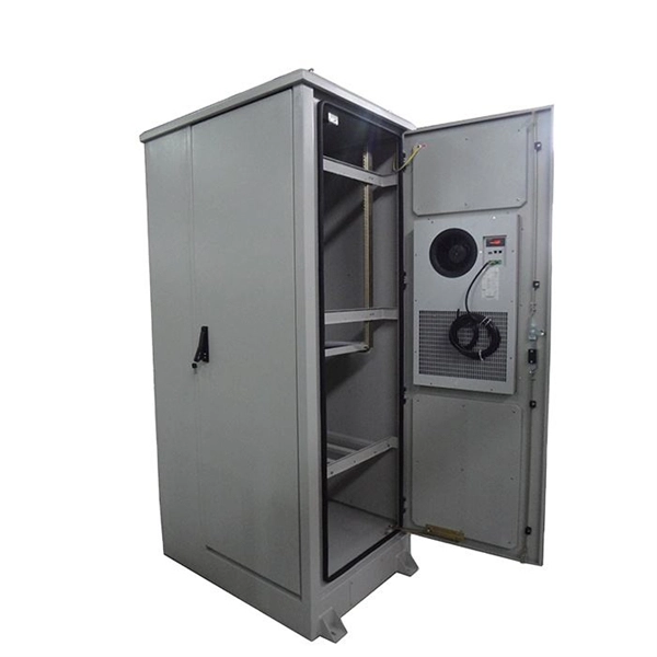
A distribution box, or DB box, is a circuit breaker enclosure. It is a vital part and central hub of any electrical system. The hub distributes electrical power from a single input source to various circuits throughout a building. Today, electrical systems are essential for homes and industries. But what exactly is a power distribution box, and why is it so essential in our daily lives? The DB panel board controls the flow of electricity. This product is part of the PacDrive 3 range, an offer of distribution boxes for Lexium 62 ILM daisy chains. This distribution block features 1 input and 4 outputs. It is a distribution box with rated supply. A power distribution box (DB box) works by serving as a central electrical panel where electrical power is received and distributed from one input source to multiple output sources. Through its design and. A distribution box, also known as a distribution board, electrical panel, or breaker box, is an enclosure that houses electrical components responsible for distributing electricity throughout a building.
[PDF]

It involves encapsulating the optical chip in a metal box filled with inert gas (usually helium) to protect the optical elements from external environmental influences and enhance heat dissipation. COB, BOX, and TO-CAN packaging each offer unique advantages tailored to specific applications. COB packaging integrates components directly onto a PCB, enabling miniaturization and cost efficiency. BOX packaging seals optical chips in a metal enclosure with inert gas, ensuring long-term stability. The COB process refers to a technology that directly mounts bare chips onto a printed circuit board (PCB), connects them via gold wire bonding, and then encapsulates and protects the chips and wires using organic adhesive. Compared with conventional processes, the COB process offers high packaging. Box, COB, and TO can are currently the most prevalent packaging forms for optical components. Box packaging, also known as hermetic sealing, has a long history. Common optical device packaging methods include COB (chip-on-board packaging), BOX and coaxial packaging. What is COB technology? COB (Chip on board) is a form of packaging that directly bonds the. The invention provides an SFP28 SR optical module structure of a COB process, and belongs to the field of optical module structures. The micro-optical module comprises a shell, an unlocking mechanism, an EMI shielding structure, a circuit board, a micro-optical module arranged at one end of the.
[PDF]

These general purpose fiber clamps provide easy means for incorporating glass or plastic optical fibers into optomechanical post assemblies or SM1-threaded components. The precision V-groove and rubber pad are designed to clamp onto the buffer of single mode or multimode fibers without damaging. Harwin supplies a range of surface-mount shield can clips to provide a straight-forward, easy-to-use board-level shielding solution. The combination of SMT clips with a shield can provides a simple and cost-effective method of shielding vulnerable or EMI-radiating board components. Harwin's shield. Check each product page for other buying options. 2-piece kit Fiber optical thermal stripper M8 & fiber optical cleaning clip compatible with bare fiber/bundle and ribbon fiber for 1-48 core dual heating mode and 8-level temperature regulation. Need help?. FPH Fiber Chucks and Holders are designed to terminate bare optical fibers and provide precise coupling and mounting within optical systems. Compatible strain relief boots and fiber clamps are also available. Clamps are larger than clips and designed to hold multiple cables and wires together. Blind plugs are used to close. 1-800-363-1992 Have any questions? Talk with us directly using LiveChat.
[PDF]

When you connect two 1000BASE-T switches with SFP ports to achieve Gigabit Ethernet, there are two methods: through standard Ethernet cable plugged into the built-in Ethernet ports of each switch, or use the SFP ports with a copper SFP module. 🎥 In this video, I show you how to connect two different branded switches using SFP modules and fiber optic cables. Whether you're using Cisco, Planet, TP-Link, D-Link, Ubiquiti, or any other brand — the key is understanding SFP compatibility. Before moving ahead, let us discuss some basics about standard Ethernet cables and 1000BASE-T (IEEE 802. Network topology refers to the way in which the links and nodes of a network are arranged in relation to each other. What Is a 10Gb SFP Module? A 10Gb SFP (Small Form-factor Pluggable) module is a compact, hot-swappable transceiver used to establish high-speed fiber. Did you swap one of the fiber connectors at one of the endpoints? Meaning, take off the housing of the fiber connector, and swap a and b. You'll find SFP / SFP+ specs on the datasheets for the switches. They're free to view and download from Cisco. Cisco also publish a GBIC /. Most modern fiber-enabled network switches require an SFP transceiver module featuring a duplex (two strand) multimode OM3 or duplex single mode OS2 connection with LC connectors. Direct attach cables with pre-terminated SFP connections may also be used. Download the Application PDF SFP transceiver.
[PDF]

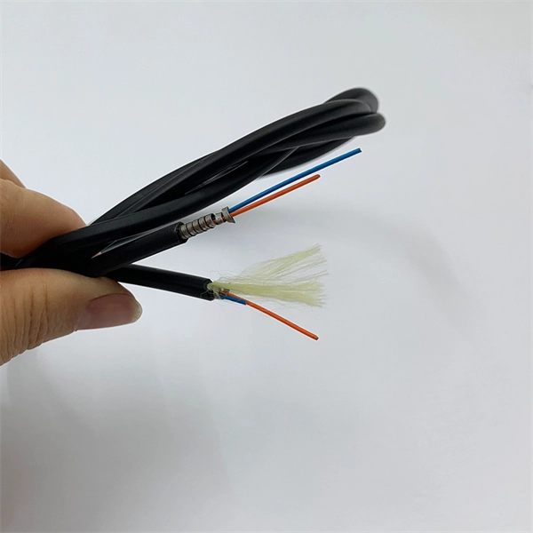
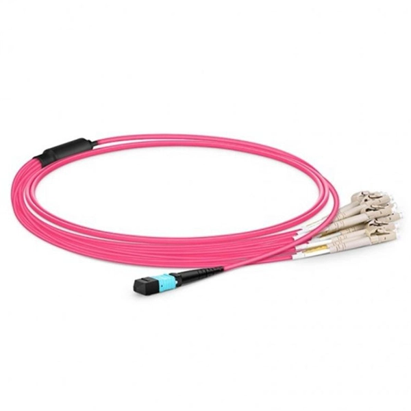
One of the core advantages of MPO patch cords is their high-density integration. Traditional patch cords have only 1-2 cores per cord, while MPO patch cords can integrate 12-48 cores, enabling multi-port connections with a single cord. Fiber cores are the heart of fiber optic cables, transmitting light signals that carry data. Made from either high-quality glass or plastic, the core plays a critical role in determining the cable's performance. The total number of cores for a 1pc fiber patch cable is calculated as the number of. Multi-core patch cords are fiber assemblies containing multiple fibers within a single cable jacket, typically available in 4, 6, 12, and 24-fiber configurations. The outer sheath is clearly marked with core count indicators. MTP/MPO cables are a class of high-density multi-core fiber optic connectivity solutions widely used in data centers and telecom networks, which are designed to achieve fast connection of multi-core fiber optics through a single interface. In the context of accelerating digitalization, the rational. The 16-core MPO patch cord, a high-density optical fiber connector, has become an ideal choice for 400G networks and beyond due to its superior optical performance, flexible compatibility, and efficient cabling capabilities. This report analyzes the key technical parameters, primary application.
[PDF]
The 3R A3140 AA serves as a fully compatible, drop-in replacement for the HCPL-3140, featuring matched performance metrics including propagation delay, CMTI, and output current, ensuring dependable real-world implementation in industrial and automation settings. The HCPL-3140/HCPL-0314 family of gate driver optocouplers consists of an GaAsP LED optically coupled to an integrated circuit with a power output stage. These optocouplers are ideally suited for driving power IGBTs and MOSFETs used in motor control inverter applications. The high operating voltage range of the. 0. Here you can find various types and values of electronic parts from the world's leading manufacturers. The HCPL-3140/A3140 components of Jotrin Electronics are carefully chosen, undergo stringent. The HCPL-3140-000E is a 0.
[PDF]