When deploying fiber optics in the field, telecommunications companies need ways to safely and efficiently store and terminate cables. As many technicians know, having the right fiber optic patch and splic.
[PDF]

Learn how to splice fiber optic cable using fusion splicing with this complete step-by-step guide. Includes tools, best practices, loss standards (ITU-T G. 652), cost analysis, and FAQs for network engineers and installers. Splicing fiber optic cable is an extremely important phase for making dependable, high-speed communication infrastructures. Regardless of the type of fiber network you're deploying, be it for telecom, enterprise data centers, or smart city infrastructure, fusion splicing provides the benefits of. Proper connection of fiber optic cables is essential to harness these benefits fully, as even minor errors can lead to significant performance issues like signal loss. This article will guide you through the necessary tools, materials, and methods on how to connect fiber optic cables effectively. Previous video we explain how to do splicing of fibers optic cable in joint closure. this video are showing how to arrange sleeves in the cable tray and arrangement of fibers. Before connecting any fiber cable, you need to assemble the proper preparation tools: With the right tools in hand, follow these key steps to achieve reliable fiber connections: 1. Strip and Clean Fiber Ends. Fiber optic internet delivers blazing-fast speeds and reliable connectivity, making it a top choice for modern homes and businesses. However, setting up a fiber optic connection to your router can seem daunting if you're unfamiliar with the process.
[PDF]
Please view our full RLH price list and contact us at info@fiberopticlink. com if you have any questions or special project needs. A 24-port patch panel is a fundamental component in modern network infrastructure, widely used by IT professionals and network installation service providers. These panels serve as centralized connection points that organize and manage Ethernet or fiber optic cabling within data centers, server. Check each product page for other buying options. Need help? Get reliable 24-port patch panels for voice, data, and video connections. Discover UL-listed options suitable for commercial and professional environments. Among the most widely used configurations is the 24 port fiber patch panel, offering an optimal balance between density and manageability. Love how customizable it is with the ability to add keystone jacks of different types. Free Shipping for many. SNTC-24X7X4 15454 - 2RU 64Ports LC Patch Panel. SP ONSITE 24X7X4.
[PDF]
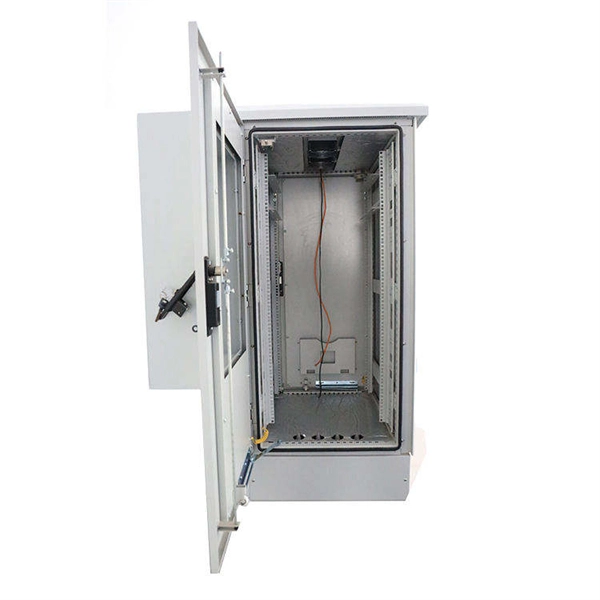
Please view our full RLH price list and contact us at info@fiberopticlink. com if you have any questions or special project needs. A Fiber Optic Patch Panel, also known as an Optical Distribution Frame (ODF) or fiber termination enclosure, is a centralized hardware unit designed to manage, protect, and organize fiber optic cable connections. In an era where data speeds and network reliability are non-negotiable, the patch. fiber optic patch panel, odf, optical distribution frame, fiber distribution panel, rack mount fiber patch panel, wall mount odf, fiber termination box, 1u fiber patch panel, 24 port fiber patch panel, 48 port fiber patch panel, outdoor fiber patch panel, fiber optic odf, sliding patch panel The. Q1: What is the difference between an ODF and a patch panel? An ODF is the entire frame or cabinet managing fiber connections, while a patch panel is a modular unit inside the ODF for cross-connecting fibers. Q2: How many fibers can an ODF handle? It depends on the ODF type; rack-mount units can. ODF is used in the terminal access link of FTTH system. It is a device that splices, distributes, and splits optical fibers and provides protection and management of optical fibers. Belden offers several Fiber Patching Systems. Full patching platforms include FX ECX for LAN environments, FX UHD for high-density fiber channels and the DCX System used primarily in data centers where high amounts of fiber connections and density are the key requirements, as in optical.
[PDF]

Receiver sensitivity is the lowest optical power level at which an optical receiver can successfully decode data with acceptable bit error rates (BER). It's a core parameter in optical transceiver specifications, indicating the module's capability to detect weak incoming signals. The standards body governing the application sets this specified BER. For example, SONET specifies that the BER must be 10 -10 or better. What Is BER? The bit error rate (BER) measures the data transmission precision within. Receiver sensitivity stands as a critical parameter impacting an optical transceiver's functionality. It denotes a module's capability to function in challenging environments and aids network operators in determining the system's maximum reach or link margin. Lower receiver. Among a group of optical receivers, a receiver is said to be more sensitive if it achieves the same performance with less optical power incident on it. The performance criterion for digital receivers is governed by the bit-error rate (BER), defined as the probability of incorrect identification of.
[PDF]

A typical fiber optic splice enclosure consists of several key components that work together to protect and organize the fiber splices. Standard enclosures contain: 1) Housing, 2) Cable fixation clamps, 3) Splice trays, 4) Sealing system. A splice box (also known as splice distributor) is a housing in which fiber optic cables begin or end. Fiber optics are fanned out in splice boxes that are situated at the end of fiber optic transmission paths. Optical cable joint box The optical cable joint box permanently connects two optical cables together and has a joint part for protecting components. The optical cable connection part, that is, the optical cable joint, is the part where the. An optical cable split fiber box, also known as a fiber distribution box or fiber optic splice closure, is a device used to terminate, splice, and distribute optical fibers. In this response, we will focus on the. This guide optimizes the original text by delving deeper into the three pillars of fiber network longevity: the impact of splicing technology, the strategic selection of splice boxes, and the essential maintenance protocols needed to ensure sustained, high-speed functionality. Fibre optic cables are manufactured in standardized lengths –.
[PDF]

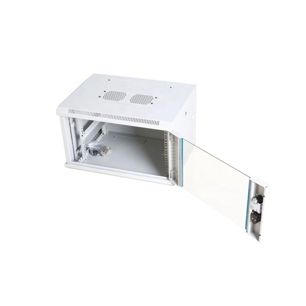
A fiber patch panel is a mounted enclosure—either rack-mounted or wall-mounted—used to terminate, manage, and interconnect multiple fiber optic cables. It acts as a hub for organizing splices and patch cords, streamlining fiber management and preserving signal integrity. Cable Organization:. Structured cabling is a standardized system to help you organize and install the cables and hardware that connect your different devices to your network (including computers, servers, cameras, or any other smart gadgets). Structured cabling uses consistent components, such as patch panels, jacks. A fiber distribution panel is also called a fiber patch panel. It helps you keep fiber optic cables neat in your network. You use this device to connect and separate fiber cables. It does not need power to work. Serving as the network's centralized junction, it provides secure ports for both incoming and outgoing. Fiber optical patch panels can help data center management cables. Do you know which types are available? What are their functions? This article will show you. With the development of data centers, the cabling infrastructure is getting larger and larger, the patch panel gives the data center a. A patch panel, including fiber patch panels and Ethernet patch panels, is a passive network device that centralizes, terminates, and organizes multiple copper or fiber cables.
[PDF]

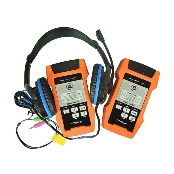
To use a power meter for fiber optic testing, always clean connectors first with lint-free wipes or click-to-clean tools. Select the correct wavelength and set your reference. You measure optical power in dBm or insertion loss in dB. Consistent procedures ensure accuracy. Verify light travels from. The most basic fiber optic measurement is optical power from the end of a fiber. This measurement is the basis for loss measurements as well as the power from a source or presented at a receiver. Typically both transmitters and receivers have receptacles for fiber optic connectors, so measuring the. An optical power meter measures the strength of light traveling through a fiber optic cable, giving you a reading in dBm (decibels relative to one milliwatt). This article will guide you through the methods, instruments, and key considerations for measuring fiber. Fiber optic cabling is the high-performance core of today's datacom networks. As network speeds and bandwidth demands increase, fiber performance requirements have become more stringent. Fiber testing is more important than ever. An OPM uses a photodiode to generate an electrical current proportional to optical power.
[PDF]
The MALD-37059 is a four channel CDR with a directly modulated laser (DML) driver for use as a transmit device in optical modules. EML: Separates the light generation function from the modulation function. It uses an external modulator to shape the signal, which improves performance in high-speed, long-distance transmission. On paper, the difference looks small. In real deployments, it can completely change the behavior of a. DML refers to a directly modulated laser. This laser is also called a distributed-feedback laser diode (DFB) since it uses a distributed feedback structure. There are two modulation techniques for optical modules, DML and EML, which are briefly introduced in this article. The optical signal transmitted in the optical fiber is not constant, but is modulated, intensity changes in the optical signal, the following is a description of the characteristics. Optical transceivers primarily adopt two mainstream modulation technologies: DML and EML. This article provides a brief introduction to both. Basic Principle of Optical Transceivers The core function of an optical transceiver is to achieve optical-electrical conversion. Ethernet layer: business as usual. 400GE or 4x100GE breakout Optical channel:.
[PDF]

The box is typically composed of several parts, including the enclosure, the splitter module, and the connectors. An optical cable split fiber box is a device used in fiber optic communication networks to split the signal from one input into multiple outputs, allowing multiple devices to be connected to a single fiber optic cable. This provides users with a dependable and high-speed network service and little to no wait times. There is no need for an FDB if there is no. In modern FTTH (Fiber to the Home) and optical communication networks, three types of fiber distribution products are widely used: Splitter Distribution Box, ODF (Optical Distribution Frame), and Fiber Terminal Box. Although they all belong to the optical distribution and management system, their. A fiber optic splitter is a passive optical component that divides a single incoming optical signal into two or more outgoing signals, or combines multiple incoming signals into one. It can divide the input optical signal into multiple output optical signals to meet the fiber optic access needs of multiple terminal devices. This type of device plays an important role in passive. In this kind of fiber cabinet, the backbone fiber optic cable usually does not connect to optical splitters. However, in some metropolitan area, the backbone fiber cable will.
[PDF]

Arduino-Powered Data Transmission with Fiber Optics Welcome to our video tutorial on optical communication with Arduino, designed to be easy t. more. They consist of a transmitter on one end of a fiber and a receiver on the other end. Most systems use a "transceiver" which includes both transmission and. I'm going to use HFBR 1414 fiber optic transmitter module which is manufactured by Broadcom. It is a low-cost high-power transmitter that is designed for use in industrial power generation, power distribution, medical transportation and gaming applications. Internally, the optical fiber consists of a highly reflective central core, which acts like a light guide. Media converters are special fiber optic transceivers used to convert from one type of cable (the media) to another, typically from copper cables to fiber optics, although some media converters will convert from one fiber type to another, e. multimode to singlemode. The FOA Guide has a page about. A fiber optic transceiver (also called an optical transceiver) is a compact module that both transmits and receives data signals through optical fibers. It serves a dual purpose — transmitting electrical signals as light pulses and receiving light pulses to convert them back into electrical form.
[PDF]

While most pigtails are single-fiber, multi-fiber options exist: Single-fiber: The most common (LC, SC, FC). Multi-fiber: 2, 4, 6, 12, 24, 48, or 72 fibers. Multi-fiber pigtails often come in ribbon format for splicing into high-count cables. Traditional Fusion Splice-On Connectors with pigtails provide factory-polished performance with field-termination convenience within harsh environments. Mass fusion splicing can fuse up to all 12 fibers in one ribbon at once. Mass Fusion Pigtails come with all 12 fibers terminated and a ribbonized. By fiber type, there are single-mode fiber optic pigtail and multimode fiber optic pigtail. And by fiber count, 6 fibers, 12 fibers optic pigtails can be found in the market. Fiber pigtails are used in an estimated 99% of single-mode fiber applications worldwide. Despite this ubiquity, they remain a source of confusion for procurement teams and junior installers alike—especially when it comes to connector type selection, polish type, and the tradeoffs between mechanical. Fiber optic pigtails can be divided into single-mode and multimode fibers. Conversely, multimode fiber pigtails, usually orange, use a 62. 5m to 2m—that has a factory-terminated connector on one end and bare fiber on the other end. The connector end is polished and tested under factory conditions, ensuring low insertion loss and high return loss.
[PDF]
Cable is usually faster than DSL as it has more bandwidth. Fiber internet, on the other hand, offers faster speeds and higher capacity overall. This is made possible because light signals travel faster and carry more information than electrical signals. Cable internet connections sit somewhere in the middle in the internet hierarchy: faster than DSL and satellite, but behind fiber. These connections utilize coaxial cables, which are made of copper, instead of fiber optic cables, which use small, flexible strands of glass or plastic. Because it's a. Whether powering a 5G network across a city or delivering gigabit internet to a rural household, fiber optic cable speed defines the backbone of digital infrastructure. This comprehensive guide explores what drives fiber optic speeds, how they compare to traditional alternatives, and how Dekam. Cable transmits data through copper coaxial cables (with an inner conductor and a protective outer jacket). Fiber-optic internet, also known as "fiber", transfers light signals along thin strands of glass.
[PDF]

The basic structure of optical fiber consists of three primary components: the core, the cladding, and the buffer coating. The core is the central part of the optical fiber through which light is transmitted. An optical fiber cable is a complex structure designed to protect fragile glass fibers that transmit digital data using light signals. This advanced cabling solution allows fast, secure data transfer and telecom over long distances. Understanding the components within a fiber optic cable enables. In this blog, we will delve into the fundamental components and structure of optical fiber to gain a better understanding of this revolutionary technology. At its core, optical fiber is a thin, flexible, and transparent fiber made of glass or plastic, which serves as a medium for transmitting light. They consist of three main components and are available in several structures suited to different uses. In this article, discover in detail these components and the various structures of fiber optic cables. The core: made of silica, molten quartz, or plastic, in which optical waves propagate. Dielectric material conducts.
[PDF]

In this tutorial by TiFi Design, you'll learn in-depth how to create. In this tutorial by TiFi Design, you'll learn in-depth how to create. In this geometry nodes tutorial, learn how to design procedural fiber optics in Blender! You'll learn in-depth how to create, distribute, and reshape splines; capture attributes; and use those attributes to build a vibrant shader. more In this geometry nodes tutorial, learn how to design. Building Information Modeling (BIM) uses multi-dimensional, spatial models that incorporate detailed product information for the building components. Blender enthusiast and YouTuber, I make video. Just wanted to share my recent geometry nodes tutorial on how to design brilliant fiber optics. I hope you enjoy it! https://youtu. be/l-OGJml_sRQ The largest. When communicating between systems, either via the internet or via an internal network system, a medium needs to be in a place that can facilitate the transmission of data, both sending and receiving. There are numerous options available for laying down communication mediums, such as coaxial cable. The Computer-Aided Design ("CAD") files and all associated content posted to this website are created, uploaded, managed and owned by third-party users. Each CAD and any associated text, image or data is in no way sponsored by or affiliated with any company, organization or real-world item.
[PDF]