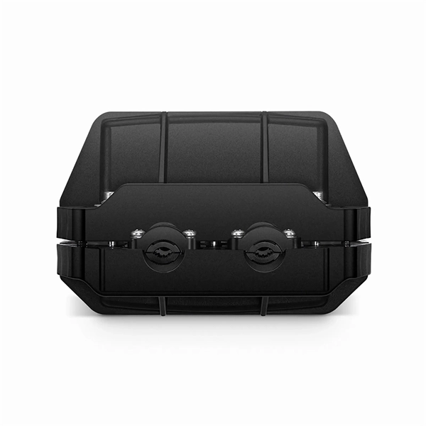
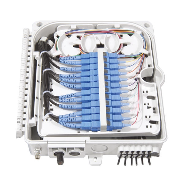
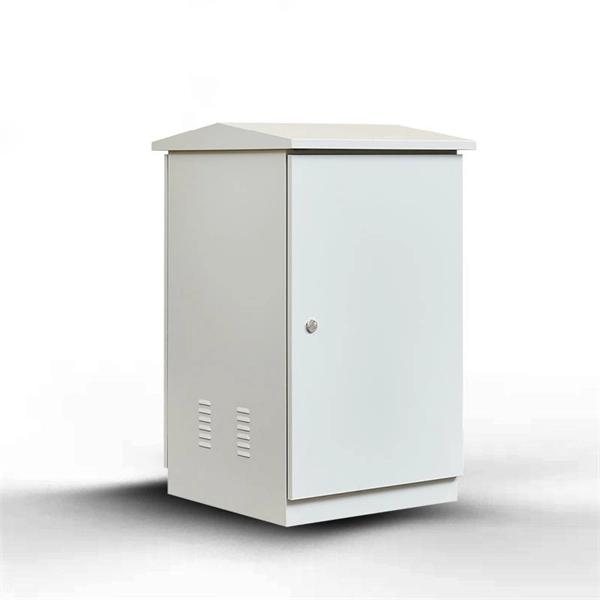
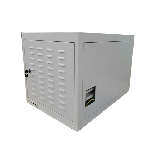
Designed without adapter slots, this enclosure provides a high-reliability, low-loss solution for environments where permanent fusion splicing is preferred over plug-and-play connections. It supports the functions of fusion splicing, optical signal splitting and fiber management. Fiber Optic Distribution Cabinet, short for FDC, is specially used for cross connect of fiber optic feeder cables and distribution cables in Fiber to the Home network. Fiber Optic. An optical distribution frame (ODF) is a frame used to provide cable interconnections between communication facilities, which can integrate fibre splicing, fibre termination, fibre optic adapters & connectors and cable connections together in a single unit. The "12C" signifies a 12-count configuration, indicating it can accommodate up to 12 fiber connections. This ODF comes pre-loaded with SC simplex. Check each product page for other buying options. Big space for managing pigtails or splitters. It is equipped with 12 SC adapters and can work in outdoor environments. Our fixed type Patch panel can be applied in the branch connection of optical fiber termination;19" standard structure, rack mounted; Available for the adapters installation of FC,SC,ST,LC. The patch panel body is made of cold rolled steel sheet. Fixed Type of Rack Mounted Standard Fiber Terminal.
[PDF]

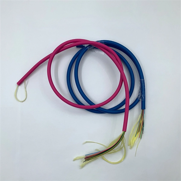
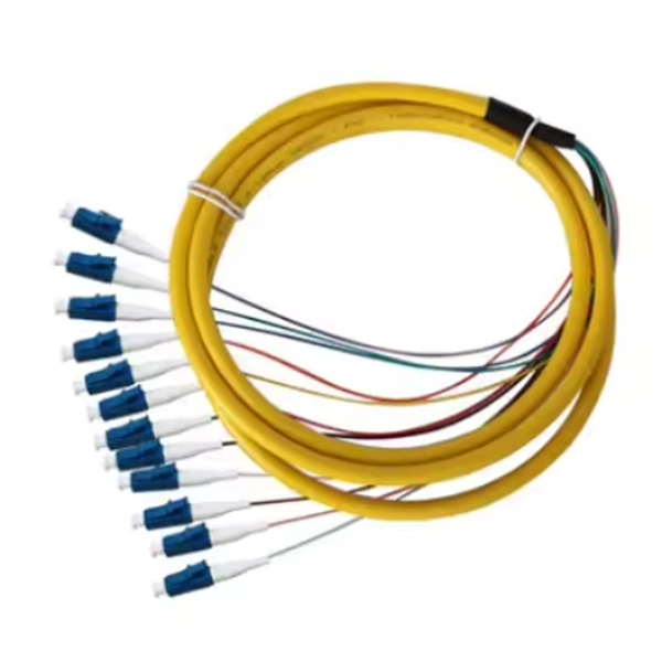
They are the bridge between fiber optic cables in the field and the equipment or patch panels that manage them. By combining factory-installed connectors with spliced bare fiber, pigtails ensure that network installers can create fast, reliable, and cost-effective terminations. Fiber pigtails are simple in appearance, yet essential in function. Get the wrong connector type, the wrong polish, or skip proper fusion splicing technique—and you're looking at elevated signal loss, increased back reflection, and a. A fiber pigtail is typically a fiber optic cable with one end factory pre-terminated fiber connector and the other exposed fiber. It is usually suitable for field termination using a mechanical or fusion splicer. Compared with quick termination or epoxy and polish connections placed on the field. ■ What is a fiber optic pigtail cable? A pigtail fiber indicates a short length of optical fiber cable that has a pigtail connector (for example, SC, FC, ST, LC, etc. ) fitted on one end and the other end undressed (for connection through fusion or splicing) to the main fiber optic cable. When compared to field-installed rapid.
[PDF]
If you're new to fiber optics or want to enhance your technical skills, this guide will help you understand how to splice fiber pigtails safely and efficiently. --- 🔧 In This Video You'll Learn: ✅ What fiber pigtails are and why they're used ✅ How to strip, clean. The most efficient way to terminate a fiber run is by using a pigtail. A fiber pigtail is a short length of optical fiber that comes with a high-quality, factory-polished connector already installed on one end, leaving a length of exposed glass on the other. Instead of building a connector from. In this detailed video, we'll walk you through the fiber optic pigtail splicing process — from preparation to final testing. --- 🔧 In. Executive Summary: A fiber optic pigtail is one of the most commonly specified yet least understood components in structured cabling. Get the wrong connector type, the wrong polish, or skip proper fusion splicing technique—and you're looking at elevated signal loss, increased back reflection, and a. Break off the cable entry from the cover and from the back box. Tie the cable to the box and wrap the fibers around the center 2~3 times as shown.
[PDF]
Most SFP fiber optic modules use LC connectors, while SC connectors are mainly found in legacy networks and MPO/MTP connectors are used for high-density cabling rather than directly on standard SFP modules. While the small size of fibre optic connectors does not mean they play a minor role, the type of connector you use affects the overall efficiency of light transmission across the fibre network. Of the more than a dozen types of fibre-optic connectors available, the four most commonly used today are. Fiber optic connectors are the unsung heroes of modern networking. They are small, often overlooked components, yet they are essential for ensuring high-speed, low-loss, and reliable optical transmission. This connector landscape reflects how modern SFP deployments prioritize port density and. A fiber optic connector is a mechanical device used to align and join optical fibers, enabling light to pass through with minimal loss. Unlike fiber splicing, which is permanent, connectors allow for easy connection and disconnection of cables, making them ideal for maintenance and flexibility in. Fiber connector types LC, SC, FC, ST, MTP, and MPO are widely used in past and present. What are the differences between them? Who is the most popular one? Find the answer in the article. As a leading provider of fiber optic solutions, Weunion understands the critical role of connectors in modern networks.
[PDF]
Featuring SC UPC connectors on both ends, it delivers low insertion loss and stable signal transmission. Its simplex structure and durable cable jacket make it suitable for a wide range of fiber optic installations. The SC/APC pre-polished fast connector comes pre-adjusted from the factory, with field-installable connectors that completely eliminate the need for hand polishing in the field. Proven mechanical splicing technology ensures precise fiber alignment, a factory-prepared fiber end, and a combination of. Technovate International Pvt. Ltd was established in 2017 with an objective to provide end-to-end fiber optic products and solutions to Internet Service Providers (ISPs) and Cable TV Operators in Nepal; and also supplying telecommunication equipment. We mostly import goods directly from our partner. Nepal - Shop for Best Online at Daraz. np Wide Variety of optic fiber sc connector. Great Prices, Even Better Service. 0mm Simplex is a high-quality fiber optic patch cable designed for reliable connectivity in telecommunications and networking applications.
[PDF]
The normal recommendation for fiber optic cable is the minimum bend radius under tension during pulling is 20 times the diameter of the cable (d). This includes pulling tension, minimum bend radius or diameter and crush loads. Installers must understand these specifications and know how to install cables without. Fiber optic cable bend radius is a critical mechanical parameter that determines how sharply a cable can be bent without risking microbending, macrobending, signal loss, or long-term structural fatigue. It is measured from the inside of the bend, not the outer curve. Fiber optic cables transmit data through light propagation within a glass core. The correct bend radius calculation is a fundamental prerequisite for high-quality fiber optic installations and is decisive for long-term network performance and reliability. While installers are aware of the fundamental importance of minimum bend radii, they often lack the practical know-how to. The bend radius of fiber cables is critical for maintaining high performance and longevity. This overview explains key standards, installation best practices, and consequences of exceeding limits during handling, routing, and management. What Is Bend Radius? You need to understand the concept.
[PDF]

This is where a small but mighty hero comes into play: the Mode Conditioning Patch Cable (MCP). In this guide, we'll demystify what a mode conditioning patch cable is, why it's essential in specific network scenarios, and how it can save you from a world of connectivity headaches. This guide offers the key technical insights you need to select and install the optimal fiber optic cabling solutions for your specific needs. Covers the basics of fiber optic technology, including how light waves transmit data through thin strands of glass or plastic, and why fiber optics surpass. Fiber optic cables use light to transmit data, whereas traditional cables rely on electrical signals, which are more prone to interference and loss over distance. Connector types play a crucial. Fiber optic technology has transformed the way we transmit data, enabling faster, more reliable connections than traditional copper cables. Understanding fiber optic cable types is essential for anyone looking to build or maintain efficient fiber networks. We'll also. This is a plain-English guide for facilities and IT teams who want fiber that performs well, stays organized, and doesn't turn every add/change into a disruption. Start with the link's distance and speed, then pick single-mode (OS) or multimode (OM)—not the other way around.
[PDF]
A fiber optic pigtail is a short length of optical fiber —typically 0. 5m to 2m—that has a factory-terminated connector on one end and bare fiber on the other end. The connector end is polished and tested under factory conditions, ensuring low insertion loss and high return loss. In this guide, we will break down what fiber optic pigtails are, how they differ from patch cords, what types exist, and how to select the right one for your project. By the end, you will have a comprehensive understanding of why pigtails deserve a place in every fiber deployment toolkit. Unlike a patch cord—which has connectors on both ends—the bare fiber end of a pigtail is designed to be permanently. The length of a fiber pigtail may seem like a simple detail, but it plays a direct role in how optical signals travel through a network. By understanding how cable length influences light transmission, installers can make better decisions that lead to stable, efficient network performance. This design allows for quick and easy splicing to another fiber or cable, ensuring a secure and efficient connection. Ideal for use in. 🔍 What Is a Fiber Pigtail? A fiber pigtail is a short length of optical fiber that has: In simple terms: A pigtail connects a connectorized interface to a permanently installed fiber via splicing. A standard FTTH.
[PDF]

Fusion Splicer Settings – Must-Know for Fiber Technicians! 🔧 At D-TECH TRADING, we're demonstrating the essential Fusion Splicer settings that every fi. more. Auto Mode is the most intuitive and user-friendly splice mode. The fusion splicer automatically detects the fiber type, such as single-mode (SM), multimode (MM), or dispersion-shifted (DS) fibers, and adjusts parameters like arc power and heating time accordingly. Applications: Ideal for beginners. Page 1 Fusion Splicer 19R+/70R+ Quick Reference Guide Splice Operation • When splicing only standard SM fibers (ITU-T G. 652), “SM AUTO” mode is recommended. It also outlines instructions for keypad usage. st Instruction manual Fusion Splicer Please read this instruction manual carefully before operating the equipment. Adhere to all safety instructions and warnings contained in this manual. Keep this manual in a safe place. There is a change without a previous notice. We are not responsible for the. Fusion splicing is the bedrock of high-performance fiber optic networks, enabling seamless signal transmission through permanent, low-loss fiber joins. As a leading provider of fiber optic infrastructure, Weunion leverages cutting-edge tools like the AI9 and AI10 fusion splicers, paired with.
[PDF]

The LC optical fiber pigtail is designed with a push-pull mechanism, enabling easy installation and removal without compromising on performance. Executive Summary: A fiber optic pigtail is one of the most commonly specified yet least understood components in structured cabling. Get the wrong connector type, the wrong polish, or skip proper fusion splicing technique—and you're looking at elevated signal loss, increased back reflection, and a. Fiber pigtails are simple in appearance, yet essential in function. They are the bridge between fiber optic cables in the field and the equipment or patch panels that manage them. By combining factory-installed connectors with spliced bare fiber, pigtails ensure that network installers can create. Fiber optic network design refers to the specialized processes leading to a successful installation and operation of a fiber optic network. It includes first determining the type of communication system (s) which will be carried over the network, the geographic layout (premises, campus, outside. All Rights Reserved. fCONSTRUCTION QUALITY REQUIREMENTS FOR FTTP & SSP Work Orders This document provides Construction Technicians, Construction Managers, FTTP/SSP Vendors, and Inspectors with the essential information to ensure a quality build and to successfully pass an Outside Plant Inspection. These terminations must be of the right style, installed in a.
[PDF]
Fiber optic color coding is an essential part of managing and working with fiber optic cables and components. The TIA-598-D standard defines a standardized color-coding system that engineers and technicians rely on to identify different types of fiber optic cables, connectors, and. Understanding fiber‑optic color codes is essential for any technician tasked with installing, maintaining, or troubleshooting modern fiber networks. But with thousands of fibers in a single cable, color coding is your universal translator. Without it, you'd be lost in a spaghetti mess. Fiber optic color knowledge is crucial for anyone working in telecommunications, networking, or data management. Yet, correctly identifying and sorting these cables is paramount in. You'll learn how to identify single-mode vs. multimode at a glance, trace individual strands in a 144-fiber bundle, and avoid the critical error of mixing connector types. In fiber optics, color isn't for decoration; it's a critical safety and efficiency tool. This standardized fiber optic color coding system helps prevent costly connection errors while dramatically.
[PDF]

The typical specification range of return loss of a fiber connector is -15 dB to -60 dB. Return loss is also known as reflection loss. It indicates the amount of signal reflected back to the transmitting end. Return loss refers to the power loss caused by the reflection of part of the signal back to the signal source during transmission due to the discontinuity of the transmission. Insertion loss, also known as attenuation, is the loss of optical power that occurs when light passes through a fiber optic connector. It is caused by factors such as misalignment, air gaps, and imperfections in the connector components. The lower the insertion loss, the better the performance of. Reflectance (which has also been called "back reflection" or optical return loss) of a connection is the amount of light that is reflected back up the fiber toward the source by light reflections off the interface of the polished end surface of the mated connectors and air. It is also called. Insertion Loss (IL) is the amount of optical power lost as the signal travels from one point to another in a fiber optic link, usually across connectors or splices. Formula for. In optical fiber communication, insertion loss and return loss are two important parameters to evaluate the quality of interfaces between some optical fiber components, such as optical fiber connector, fiber patch cable, pigtail fiber, etc. While it's natural to have.
[PDF]

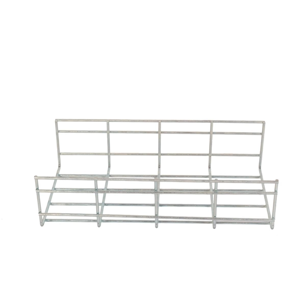
This guide covers everything: what fiber optic pigtails are, how they differ from patch cords, which connector and polish type to specify, how to choose between mechanical and fusion splicing, and the real-world applications where pigtails are the right call. Whether you're building out an ODF. Optimize your cable management with our slotted wall cable routing channel. The slotted design allows for easy access and routing, ensuring secure and efficient installations. They are the bridge between fiber optic cables in the field and the equipment or patch panels that manage them. By combining factory-installed connectors with spliced bare fiber, pigtails ensure that network installers can create. The fiber optic pigtail is a short terminated optical fiber with a connector on one end, used to facilitate easy connections between fiber optic cables and various devices. This article will show you what a fiber optic pigtail is. The success of a network in fiber optic cable installation heavily. The Fiber Optic Pigtail is a foundational component in modern telecommunications, serving as the critical link for terminating fiber optic cables. The connector end plugs into devices like transceivers or patch panels, while the bare end is typically fusion spliced to a fiber optic cable. This setup ensures.
[PDF]
This article will guide you through the process of troubleshooting fiber optic connections, with a focus on ensuring proper TX and RX alignment and how to correctly switch patch cables to resolve issues. This document describes how to troubleshoot fiber optic interfaces by addressing some of the fiber optic module and cabling specifications. There are no specific requirements for this document. The information in this document is based on all Catalyst 9000 Series switches. This includes Doppler. Fiber optic networks are celebrated for their speed and reliability, but even the best systems can encounter problems. When issues like signal loss, slow speeds, or intermittent connectivity arise, systematic troubleshooting is key. 8750) Description: Internet address is. There is a single mode optical fiber cable in our datacenter going from a Cisco N5K to another N5K across different racks. The link appears to be dead and I'm hoping to fix it, but I have little to no experience with fiber. The LED light of the SFP+ ports on both switches are off (not lighting up).
[PDF]
In this paper, we propose and experimentally demonstrate a Michelson interferometer (MI)-based inclinometer using a simple configuration: a misalignment-spliced single mode fiber (SMF) with end coating. A fiberoptic sensor that uses diverse fiber units to support various applications in virtually any environment. These are reliable and easy-to-use devices that have high power, can automatically adjust to real-time conditions, and have a straightforward display that eliminates any guesswork. This. An in-fiber Michelson interferometer (MI)-based inclinometer, which consists of misalignment-spliced fiber with end coating, is proposed and experimentally demonstrated. The incident light divided at the misalignment-spliced joint is reflected at the end coating, and then re-coupled into the fiber. Jose Miguel Lopez-Higuera: Handbook of Optical Fiber Sensing Technology, John Wiley & Sons, 2002. P 603 Radiation absorption excites an orbital electron to a higher energy level.
[PDF]