In this informative video, learn how to seamlessly integrate fiber optic cables with Power over Ethernet (PoE) systems for enhanced connectivity and performance. This installation guide focuses on what a patch panel does, patch panel installation basics, and how to connect patch panel to switch while keeping cabling clean and easy to manage. Switch: What's the Difference? Although a patch panel and a switch can look similar in a rack, they. Fiber patch panels are important components that are used to help organize and protect fiber optic cables. Connecting a fiber patch panel to a switch is a critical step in setting up a fiber optic network. Identify. If the PoE switch has SFP slot built-in, what you need is the SFP module installed in the slot. Firstly, Insert the SFP module into PoE switch's SFP slot. Discover the advantages of using fiber optic cables in conjunction with PoE and gain insights into the necessary components required for. If you have an existing patch panel the short answer to “can I just plug in a cable into the front of it” is yes. In comparison to wiring up individual networks, patch panels are much more efficient and can provide more reliable, faster connections. This article will.
[PDF]

The primary function of a fiber adapter panel is to provide a housing for fiber optic adapters or connectors. These adapters act as the interface between the terminated fiber ends and the active equipment, such as switches, routers, or servers. A fiber patch panel is a mounted enclosure—either rack-mounted or wall-mounted—used to terminate, manage, and interconnect multiple fiber optic cables. It acts as a hub for organizing splices and patch cords, streamlining fiber management and preserving signal integrity. This guide will focus on elucidating the aspects of the fiber patch panel, its accessories, the work done with such a device, and how to. Fiber optic networks are the backbone of fast, reliable internet and modern communications, but even the best fiber cables need the right connectors and patch panels to work efficiently. Connectors are the points where fiber cables link to devices, equipment, or other cables, and using the right. The fiber optic patch panel, also known as the fiber distribution panel, serves as the crucial component of the management of fiber optic cables. Also, the advantage of fiber optic patch panels is to reduce the loss of fiber optic transmission and facilitate engineers to troubleshoot. Serving as the network's centralized junction, it provides secure ports for both incoming and outgoing fibers, streamlining connection.
[PDF]

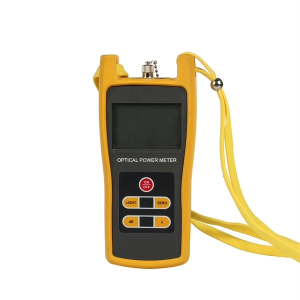
The max insertion loss of a fiber patch cable is 0. 75 dB (the maximum acceptable value) in the TIA standard. Insertion loss (IL) and return loss (RL) are key performance indicators of fiber optic patch cords. This article explains their concepts, standards, testing methods, and FiberMania's quality assurance workflow to ensure optimal network performance. Fiber optic patch cords are crucial components in. A: Fiber optic loss refers to the reduction in signal strength as it travels through the fiber optic cable. This can be due to various factors, including attenuation, connectors, and splices. Q: How is fiber optic loss measured? A: Fiber optic loss is typically measured using an Optical Loss Test. The estimate, called a "loss budget" is calculated using typical component losses for each part of the cable plant - the fiber, splices and/or connectors. If the measured loss exceed the calculated loss by a significant amount (remembering the inherent uncertainty in all measurements), the system. Insertion loss is usually shortened to IL, and the unit of measurement for insertion loss is dBm. ) in transmission systems. It is the power attenuation of the signal after. At TARLUZ, we specialize in manufacturing high-performance fiber optic patch cords that comply with global industry standards, ensuring optimal signal integrity and long-term stability.
[PDF]

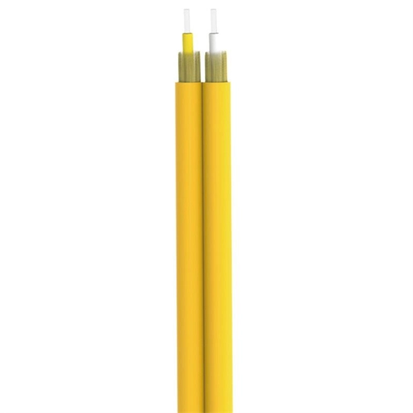
Multi-mode fiber optic patch cords utilize a larger core size, typically around 50-100 microns, allowing them to carry multiple modes of light. This design enables the transmission of data over relatively short distances with high bandwidth capabilities. A fiber-optic patch cord is a fiber-optic cable capped at each end with connectors that allow it to be rapidly and conveniently connected to telecommunication equipment. This is known as interconnect-style cabling. A fiber-optic patch cord is constructed from a core with a high refractive. These short fiber optic cords connect transceivers, switches, patch panels, and servers. Without them, even the best optical modules and switches cannot deliver performance. As data rates increase from 10G → 100G → 400G → 800G, patch cables must handle more bandwidth, more density, and stricter. Fiber optic patch cords, also known as fiber optic patch cables or fiber jumpers, are indispensable components in modern optical networks. They act as the critical link for interconnecting devices like optical switches, servers, and distribution frames. Understanding the various technical. Fiber patch cables, also called fiber-optic patch cords, are cables typically containing one or two optical fibers, which are equipped with standardized fiber connectors on both ends. The function of the fiber patch cord.
[PDF]

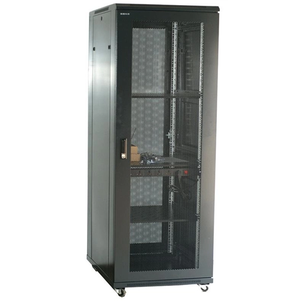
A fiber patch panel is a mounted enclosure—either rack-mounted or wall-mounted—used to terminate, manage, and interconnect multiple fiber optic cables. It acts as a hub for organizing splices and patch cords, streamlining fiber management and preserving signal integrity. Cable Organization:. Structured cabling is a standardized system to help you organize and install the cables and hardware that connect your different devices to your network (including computers, servers, cameras, or any other smart gadgets). Structured cabling uses consistent components, such as patch panels, jacks. A fiber distribution panel is also called a fiber patch panel. It helps you keep fiber optic cables neat in your network. You use this device to connect and separate fiber cables. It does not need power to work. Serving as the network's centralized junction, it provides secure ports for both incoming and outgoing. Fiber optical patch panels can help data center management cables. Do you know which types are available? What are their functions? This article will show you. With the development of data centers, the cabling infrastructure is getting larger and larger, the patch panel gives the data center a. A patch panel, including fiber patch panels and Ethernet patch panels, is a passive network device that centralizes, terminates, and organizes multiple copper or fiber cables.
[PDF]
Please view our full RLH price list and contact us at info@fiberopticlink. com if you have any questions or special project needs. A Fiber Optic Patch Panel, also known as an Optical Distribution Frame (ODF) or fiber termination enclosure, is a centralized hardware unit designed to manage, protect, and organize fiber optic cable connections. In an era where data speeds and network reliability are non-negotiable, the patch. fiber optic patch panel, odf, optical distribution frame, fiber distribution panel, rack mount fiber patch panel, wall mount odf, fiber termination box, 1u fiber patch panel, 24 port fiber patch panel, 48 port fiber patch panel, outdoor fiber patch panel, fiber optic odf, sliding patch panel The. Q1: What is the difference between an ODF and a patch panel? An ODF is the entire frame or cabinet managing fiber connections, while a patch panel is a modular unit inside the ODF for cross-connecting fibers. Q2: How many fibers can an ODF handle? It depends on the ODF type; rack-mount units can. ODF is used in the terminal access link of FTTH system. It is a device that splices, distributes, and splits optical fibers and provides protection and management of optical fibers. Belden offers several Fiber Patching Systems. Full patching platforms include FX ECX for LAN environments, FX UHD for high-density fiber channels and the DCX System used primarily in data centers where high amounts of fiber connections and density are the key requirements, as in optical.
[PDF]
You might have bad connections or lose signal if you bend them too much. Rough handling can also cause problems. Clean them often and manage them with care to stop these issues. If you act early, you will have less downtime. Your network will work better and stay smooth. Proper installation and regular maintenance of fiber optic patch cords play a crucial role in achieving optimized network performance, preventing signal errors, and extending service life. This guide addresses expert-certified best practices applied by professionals in the telecommunications, data. Patching operations must follow principles of neatness, aesthetic cabling, ease of operation, and minimal space usage within ODF frames, optical cross-connects, and integrated boxes. Patch cable lengths should be controlled with a surplus of no more than 500mm. Never use patch cables that are too. Effective fibre optic cable management is crucial for ensuring network reliability, performance, and long-term efficiency. Poorly routed cables, inadequate strain relief, and excessive bending can result in signal loss, increased maintenance, and costly downtime. Incorrect cable lengths can lead to signal attenuation, which refers to the loss of signal strength as it travels through the cable. Plan your fiber patch cord.
[PDF]
Answer: Ducts and bends choke bulky connectorized heads; long pulls would damage ends; and cumulative connector loss kills your budget. Splice pigtails locally; patch with jumpers on the front. Key. A fiber optic patch cord is a short-length cable (typically 1–10 meters) with pre-terminated connectors on both ends. Its primary function is to connect active network devices (e., switches, routers, transceivers) to passive components (e., patch panels, ODFs) or other devices. They act as the critical link for interconnecting devices like optical switches, servers, and distribution frames. Understanding the various technical. When designing a fiber network, one of the most common questions is: Should you use fiber optic pigtails or patch cords? While they may look similar, their functions are very different—and choosing the wrong one can impact performance and installation efficiency. Without them, even the best optical modules and switches cannot deliver performance. As data rates increase from 10G → 100G → 400G → 800G, patch cables must handle more bandwidth, more density, and stricter. A fiber optic patch cord (fiber jumper) is: Typical applications: A patch cord is the “bridge” that connects two fiber devices and lets them talk to each other. ZION Communication supplies both standard patch cords and custom assemblies to match your equipment, distance, and installation.
[PDF]

1000BASE-SX is a gigabit Ethernet standard over fiber optic for short reach. It is used for operating on multimode fiber with a short wavelength of 770 to 860 nanometers (typically 850nm). The “SX” stands for short reach over multimode fiber. 1000BASE-SX defines a maximum length of 220 meters for. What Is An Sx Sfp Module? The Ultimate Guide To 1G Transceivers (Sx Vs Lx Vs Sr) If you are buying fiber optic transceivers for a network upgrade, the alphabet soup of acronyms can be a nightmare. You see SX, LX, SR, LR. and they all look like the same little metal box. But choosing the wrong one. A Beginner's Guide: What is 1000BASE-SX, 1000BASE-LX & 1000BASE-ZX? Gigabit Ethernet (GbE) has gained significant popularity and is widely used in enterprise network backbones. It's defined by IEEE standards 802. These standards are vital for Ethernet's physical layer and. 1000Base-SX is a type of standard for implementing Gigabit Ethernet networks. The SX in 1000BaseSX stands for short, and it indicates that this version of Gigabit Ethernet is intended for use with short-wavelength transmissions over short cable runs of fiber-optic cabling. The application's nominal symbol rate is 1. 25 GBd per lane and the supported distance varies according to the type of multimode cable used. These modules convert electrical signals from.
[PDF]

Even when a network is designed correctly, real-world conditions—fiber handling, connector cleanliness, splices, environmental stress, and aging—can gradually increase attenuation or introduce reflections and interference. Fiber optic patch cords are often treated as low-risk consumables, yet a large percentage of optical link failures originate at the patch cord level. Unlike backbone cables, patch cords are frequently connected, disconnected, bent, and handled by technicians, making them the most vulnerable. Optical attenuation is the gradual loss of flux (light intensity) as an optical signal travels through a fiber. Measured in decibels (dB), it's the logarithmic ratio of the output power to the input power. Every network has a "loss budget". Field guide for diagnosing high fiber optic attenuation. Learn to use the OTDR to identify contamination, micro-bends, and poor splices, ensuring your 400G network links remain within budget. This article explains practical, engineering-focused ways to mitigate signal. This measurement helps determine the efficiency of a fiber optic system. Several factors contribute to signal attenuation. These include absorption, scattering, and bending losses. Each factor plays a significant role in the overall performance of a network. Whether you're a network engineer, IT manager, or service provider, understanding these challenges and how to address them is critical for maintaining high-performance, reliable.
[PDF]

Choosing the right fiber type, typically single-mode, enhances the performance of 1310nm modules, allowing for longer transmission distances. 1310nm lasers support various data rates, from 1Gbps to 100Gbps, providing flexibility for different network needs. In fiber-optic communication, a single-mode optical fiber, also known as fundamental- or mono-mode, is an optical fiber designed to carry only a single mode of light - the transverse mode. When selecting a module, consider factors. Single-mode fibers (also called monomode fibers) are optical fibers which are designed such that they support only a single propagation mode (LP 01) per polarization direction for a given wavelength. Higher-order modes like LP 11, LP 20 etc. then do not exist — only cladding modes, which are not. Gigabit single-mode fiber optic module Common parameters of optical modules 1. Center wavelength 1) 850nm (MM, multi-mode, low cost, but short transmission distance, usually only 500M); 2) 1310nm (SM, single mode, large loss during transmission, small dispersion, generally used for transmission. Single mode fiber (SMF) is a type of fiber optic cable that only allows one light mode to transmit at a time. Generally, single mode cable has a narrow core diameter of 8 to 10µm (micrometers), which can propagate at the wavelength of 1310nm and 1550nm. They feature low attenuation benchmarks 2 and minimal dispersion. They use OS1 or OS2 OS1 or OS2 classifications to.
[PDF]

This guide covers the essential tools and step-by-step procedures for low-loss fiber optic cable repair. Understanding the causes and types of fiber optic cable damage helps detect issues early and determine when repair is needed. Construction Activities: Accidental damage during construction. Step1 : Identify the optical cabinet and network operating center, and find the fiber optic splitter. Step 2: Identify the splitter number. Step 4: Find the optical fiber port and cable sequence that leads to the user. 2) The. This complete guide covers everything from identifying causes of failure to advanced repair techniques, drawing on the latest industry standards and innovations. Whether you're a network technician, IT professional, or telecom operator, you'll find practical steps, tools, and tips to restore. If you accidentally break a fiber optic patch cord in your server room or in any of your switch gear, now you can repair it on the spot and get back up and running in minutes. Adhering to precise methodologies, we can mend impaired cables. By understanding these key elements and following the outlined steps, you can effectively repair fiber optic cables and maintain the high-performance network necessary for today's demanding communication needs. When it comes to ensuring nice network experiences for users, the condition of a fiber.
[PDF]

In this tutorial by TiFi Design, you'll learn in-depth how to create. In this tutorial by TiFi Design, you'll learn in-depth how to create. In this geometry nodes tutorial, learn how to design procedural fiber optics in Blender! You'll learn in-depth how to create, distribute, and reshape splines; capture attributes; and use those attributes to build a vibrant shader. more In this geometry nodes tutorial, learn how to design. Building Information Modeling (BIM) uses multi-dimensional, spatial models that incorporate detailed product information for the building components. Blender enthusiast and YouTuber, I make video. Just wanted to share my recent geometry nodes tutorial on how to design brilliant fiber optics. I hope you enjoy it! https://youtu. be/l-OGJml_sRQ The largest. When communicating between systems, either via the internet or via an internal network system, a medium needs to be in a place that can facilitate the transmission of data, both sending and receiving. There are numerous options available for laying down communication mediums, such as coaxial cable. The Computer-Aided Design ("CAD") files and all associated content posted to this website are created, uploaded, managed and owned by third-party users. Each CAD and any associated text, image or data is in no way sponsored by or affiliated with any company, organization or real-world item.
[PDF]

The main components of a splice box are the splice cassette that picks up the fibers and their reserves, and the front panel which contains different connectors for transmitting signals via copper or fiber optic cables. A splice box (also known as splice distributor) is a housing in which fiber optic cables begin or end. Fiber optics are fanned out in splice boxes that are situated at the end of fiber optic transmission paths. It typically consists of two parts: an outer housing and an internal structure. In this response, we will focus on the. The FSB series of indoor wall mount enclosures are designed for centralized splice-only applications. These boxes are well suited as optical cable splice collection points for DAS (Distributed Antenna Systems), MTU (Multi-Tenant Unit) commercial business applications, and MDU (Multi-Dwelling Unit). Fiber optic splice closures permanently connect two fiber optic cables together and have a splice that protects the components. The optical cable connection part, that is, the optical cable joint, is the part that protects the connection between two or more optical cables by the optical cable. Splicing refers to the permanent connection of two optical fibers to form a continuous optical connection.
[PDF]

Optical fibers or fiber cables can be used for transmitting optical power from a source to some application. In their served areas will be power generating stations, alternative energy sources (solar, wind, geotherman, etc. ), substations for distribution and microgrids. These networks must be monitored and managed to ensure reliable power for the utility's customers. For monitoring and managing networks. Low voltage cables are mounted on poles in the "telecom space," well below power cables. Optical power ground wire (OPGW) is an electrical power ground with fiber optics in the center of the conductor. That conversion can be done with a photovoltaic cell. The Commission, on June 22, 1965, noting that the increasing demand for underground electric and communication facilities in California has brought about substantial increases in the construction of such facilities, and that it appeared it may be desirable, pursuant to Sections 761, 768 and 8056 of. One choice is optical power ground wire (OPGW). This conductive cable is run at the top of the tower or pole to be the ground conductor and protect the power cables from lightning. The fiber. While fiber optics is essential for internet service providers to deliver higher bandwidth and faster transmit speeds, there are also many crucial benefits of fiber optics in energy and power. Utility companies face various challenges as they work to deliver reliable energy to homes and industries.
[PDF]