Distance relays, also known as impedance relay, differ in principle from other forms of protection in that their performance is not governed by the magnitude of the current or voltage in the protected circuit but rather on the ratio of these two quantities.OverviewIn, a protective relay is a device designed to trip a when a is detected. The first protective relays were electromagnetic devices, relying on coils operating on moving par. Electromechanical protective relays operate by either, or. Unlike switching type electromechanical with fixed and usually ill-defined operating voltage thresholds. Electromechanical relays can be classified into several different types as follows: "Armature"-type relays have a pivoted lever supported on a hinge or knife-edge pivot, which carries a moving contact. These relays may.
[PDF]
Fiber optic pressure sensors operate based on the principle of light modulation in optical fibers. When pressure is applied to the sensing element, it changes the properties of the fiber, such as the refractive index or the intensity of the light. These sensors are gaining popularity. Fiber-optic sensing (FOS) technology has emerged as a cutting-edge research focus in the sensor field due to its miniaturized structure, high sensitivity, and remarkable electromagnetic interference immunity. Compared with conventional sensing technologies, FOS demonstrates superior capabilities in. This article explains the structure, working principle, advantages, and disadvantages of Fiber Optic Pressure Sensors. Compared to traditional electronic pressure sensors, they offer advantages such as immunity to. Fiber optic pressure sensors are transforming how industries monitor and manage critical systems. Unlike traditional sensors, these devices use light to measure pressure changes, offering high accuracy, immunity to electromagnetic interference, and durability in harsh environments.
[PDF]
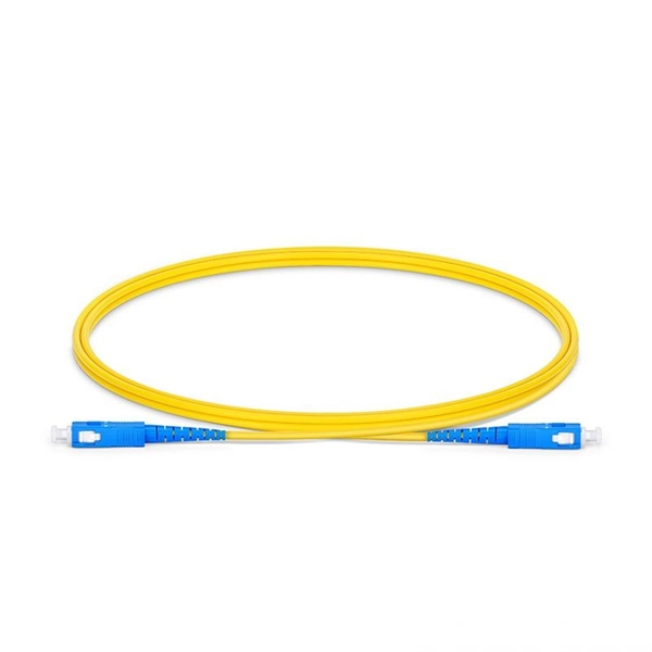
Fiber optic patch cords do not have “polarity” in the sense of electrical positive and negative terminals, like a battery. Plugging them in “backwards” will not cause a short circuit, and it will not burn out or damage your equipment. Patch cord polarity defines the directional optical path between two transceivers, ensuring that the transmit (Tx) signal from one device reaches the receive (Rx) port of the other. Patch cables for fiber optic can have the same connector on each end (e. Since fiber optic links require a two-way - or duplex - connection, there is potential for errors in installation by connecting transmitter to transmitter or. As networks move to higher speeds and higher density, choosing the right fiber optic patch cords becomes critical to the reliability of your system. At ZION Communication, we design and manufacture a full range of fiber patch cords for: This guide will help you quickly understand the main types of. Negative poles have a greater number of electrons relative to positive poles; when connected, electric current will flow from negative to positive. When used in the context of fiber-optic communication, this is analogous to the flow of data in the form of light signals from transmit (Tx) to receive. Simplex optics: A single fiber is used to plug things in and establish transmit and receive one one fiber in one direction. Parallel optics: Multiple fibers used to establish higher.
[PDF]

Diagram showing positive tip polarity on the left and negative tip polarity on the right. To read diagram: The center positive drawing on the left indicates that the center (also known as the tip) of the output plug is positive (+) and the barrel (ring) of the output plug is negative. The center positive drawing on the left indicates that the center (tip) of the output plug is positive (+) and the barrel of the output plug is negative (-). Symbol for a center-positive power supply. It is always good practice to test. The term positive terminal describes which of the two connection terminals on direct current (DC) equipment supplies or is meant to receive a positive electrical charge. DC power supplies always feature a positive to negative electron flow and always have a negative and positive terminal. Polarity. It is defined by the positive and negative terminals of a power source, such as a battery. Understanding polarity is essential because connecting a device to a power source with the correct. The rating plate of an Extra Low Voltage Power Supply (ELVPSU) shows various symbols and abbreviations. These represent critical information about the supply's ratings, class, polarity, and other safety details. The polarity symbol indicates if the centre (or tip) of the output plug is positive (+).
[PDF]
