Bend insensitive fiber patch cable is designed to transmit light with minimum loss even if they are bent beyond the bend radius. Fiber optic patch cords are often treated as low-risk consumables, yet a large percentage of optical link failures originate at the patch cord level. Unlike backbone cables, patch cords are frequently connected, disconnected, bent, and handled by technicians, making them the most vulnerable. The bend radius of fiber cables is critical for maintaining high performance and longevity. During installation under tension, maintain a minimum bend radius of 20 times the cable's outer diameter, while post-installation requires a minimum long-term bend radius of 10 times the cable diameter. Fiber optic cables are designed to withstand some bending, but excessive bends can physically damage the glass fiber or cause significant signal loss. That's why every fiber cable has a minimum bend radius specification provided by the manufacturer. The minimum bend radius defines the smallest. When fiber optic cables are bent more sharply than recommended, the internal fibers can break or develop micro-fractures, leading to: Reduced Signal Quality: Noticeable deterioration in signal transmission, including lower speeds and data loss, often results from bending-induced damage. As the bending becomes more acute, more light leaks out (shown in the picture below).
[PDF]
Yes, you can often use your existing router with fiber optic internet, but there are crucial considerations. Understanding compatibility, potential limitations, and when an upgrade is necessary will ensure you get the most out of your high-speed connection. Fiber internet transmits data using light signals through fiber-optic cables, which differs from traditional DSL or cable internet. Instead of a modem, fiber connections require an Optical Network Terminal (ONT), a device that converts fiber signals into an Ethernet connection. Most fiber ISPs. While routers are designed to connect to a modem, the type of modem and the connection protocol are where compatibility with fiber becomes a crucial consideration. There are several types of connectors, including LC, SC, and ST. When you connect. The fiber optic cable does not plug directly into a standard home router because the signal type must be translated. This specialized equipment serves as the.
[PDF]
In STP, copper wires are first covered by plastic insulation. A metal shield, which consists of metal foil or braid, surrounds the bundle of insulated pairs. Where electromagnetic radiation is a serious issue, eac.
[PDF]

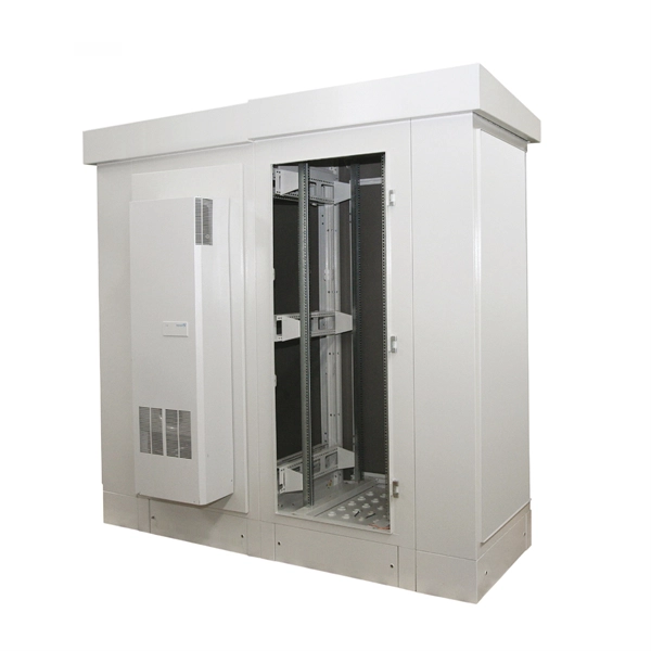
This guide provides a complete breakdown of enclosure types, materials, certifications, temperature considerations, and installation insights to help engineers, designers, and safety professionals select enclosures that meet both operational and regulatory demands. Explosion-proof enclosures are used by such facilities to ensure the safe housing of electrical components that could cause a spark and ignite these gases in the atmosphere. What Is An Explosion Proof Box or Enclosure? They are a cast aluminum or iron box that can withstand a heavy-duty explosion. Explosion-proof and flameproof equipment is essential for safe operation in hazardous (classified) locations where flammable gases, vapors, or combustible dusts may be present. What Are Hazardous Area. Pepperl+Fuchs provides a specialized portfolio of Ex d (flameproof) and Ex tb (dust protection by enclosure) certified terminal boxes and junction boxes engineered for reliable use in explosion-hazardous areas. These sturdy solutions are certified according to global standards such as ATEX, IECEx. Blast-proof enclosures are protective devices designed to prevent the consequences of fires & explosions. Such structures are specially configured to be pressure vessels hence they can contain internal pressure without propagating it. Rather than stopping an explosion from occurring, the equipment safely manages it within a reinforced structure. Common protection methods include: These principles are.
[PDF]
Optical fibers can be used as sensors to measure, , and other quantities by modifying a fiber so that the quantity to be measured modulates the,,, or transit time of light in the fiber. Sensors that vary the intensity of light are the simplest, since only a simple source and detector are required. A particularly useful feature of intrinsic fiber-optic sensors is that they can, if required, provide distributed sensing over very large distances.
[PDF]
The answer is yes, and it's a practice widely used in the industry to distribute signals to multiple destinations without degrading the signal quality significantly. This article delves into the methods, benefits, challenges, and practical applications of splitting fiber lines. A fiber optic splitter is a passive optical component that divides a single incoming optical signal into two or more outgoing signals, or combines multiple incoming signals into one. Its primary role is in Passive Optical Networks (PON), which are the foundation of. Fiber splitters are critical in optical networking, skillfully dividing a single light signal into multiple outputs for diverse applications. Their passive operation allows for widespread use in telecommunications, data distribution, and sensor systems, making them a backbone technology in. Power splitters (also commonly called “optical splitters”) are devices that divide an optical signal into multiple, equal-intensity output signals. The split ratios are usually even, like 1:2, 1:4, 1:8, and up to 1:32. Other split ratios are available, but usually come at a higher cost as they have. An optical splitter is a passive bidirectional element, which is used to connect a large number of subscribers/ONUs to an OLT. It is one of the most important elements of all FTTx PON and OLAN networks. What is Fiber Line.
[PDF]

Cable laying services install fiber optic cable or copper cable in buildings and office complexes, or over large distances. They are staffed by cable technicians who perform cable preparation, jointing, termination, testing, commissioning, maintenance, and troubleshooting tasks. Installing fiber optic cables underground involves far more than digging trenches and placing cables. It forms a critical backbone for modern communication networks across both urban and rural environments. Project success depends on careful planning, precise installation practices, and proper. Installing underground fiber optic cables is critical to establishing high speed internet infrastructure that delivers reliable connectivity for businesses nationwide. Unlike traditional copper systems, fiber optic cables require specialized handling techniques and precise installation methods to. These skilled professionals ensure that your home or business is equipped with the latest fiber optic technology, providing blazing-fast Internet speeds and robust connections. This guide walks you through the entire process of fiber cable installation, from the initial assessment to the final. This involves burying or installing fiber-optic cables along predetermined routes. During this phase, locators identify existing utilities to prevent damage.
[PDF]

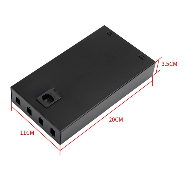
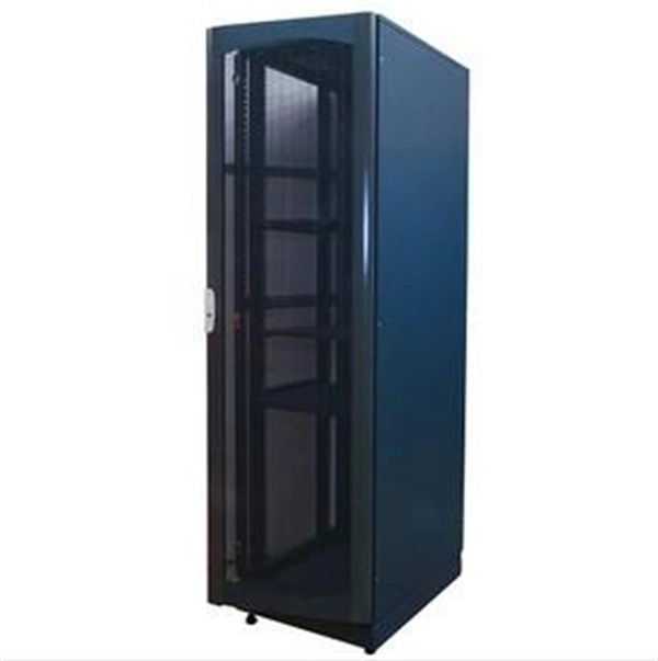
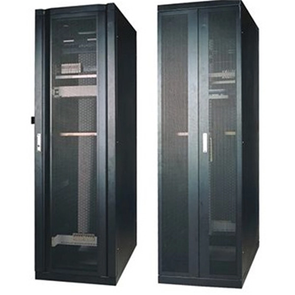
The compact 1 port ftth fiber termination box can hold 2 cores splicing, termination and coil up to 30 meters long for cable management in FTTH network. The 1 port fiber termination box is available for fiber optic cable coiling, it is great to connect optical cable and pigtail and protect fiber splices from damage. It is small, lightweight, and offers the function of fiber splicing, storage, and termination, mainly used in residential buildings. The maximum distance for single mode fiber optic cable can extend up to several hundred kilometers, making it ideal for long distance data transmission. One type of single mode fiber is known as “G. 652,” which is commonly used in telecommunications networks. Here are some general guidelines: 1. The shorter distance accounts for the. A fiber optic distribution box (FDB) is a protective enclosure for managing fiber optic cables. It organizes connections, splices fibers, and distributes signals in networks like FTTH (Fiber-to-the-Home) or FTTB (Fiber-to-the-Building). It acts as a central point for terminating, splicing, and distributing these cables, providing necessary protection and. The Fiber Optic Association, Inc. (FOA) was founded in 1995 to help develop the workforce to build the fiber optic networks to support a rapid expansion in communications and the Internet. The charter of the FOA was to promote professionalism in fiber optics through education, certification, and.
[PDF]
With the large variety of beamsplitters available, the designer needs to take many factors into consideration. This article and its illustrations will go a long way toward making the correct choice less of a risk. All curves show typical performance. A beam splitter (or beamsplitter, power splitter) is an optical device which can split an incident light beam (e. a laser beam) into two (or sometimes more) beams, which may or may not have the same optical power (radiant flux). It is a crucial part of many optical experimental and measurement systems, such as interferometers, also finding widespread application in fibre optic telecommunications. One beam is typically reflected while the other is transmitted. Beamsplitters are often classified according to their construction: cube or plate. In this blog, we will explore the step-by-step process of using a beamsplitter cube effectively, along with some common applications that benefit from this powerful optical tool. Step-by-Step Guide on Using a Beamsplitter Cube Step 1: Understanding the Cube Orientation: A beamsplitter cube is a. A beam splitter is an optical device that splits beams (such as laser beams) into two (or more) beams. Beam splitters typically come in the form of a reflective device that can split beams into exactly 50/50, half of the beam being transmitted through the splitter and half being reflected.
[PDF]
Corning's ClearCurve bend-improved single-mode fibers provide lower cost, superior installation speed and efficiency, and greater successful installations. 15dB ultra low IL fiber optic cable is less attenuation when bent or twisted compared with traditional bend insensitive fiber cables and this will make the installation and maintenance of the fiber optic cables more efficient. Their market growth is directly tied to the expansion of high-speed internet access and innovative data transmission methods. The global fiber optic cable market is. Gain in-depth insights into Bend Insensitive Fiber Optic Cable Market, projected to surge from $ 1. 5 Bn by 2033, expanding at a CAGR of 7. Explore detailed market trends, growth drivers, and opportunities. 5 USD Million in 2024. The Bend Insensitive Fiber Optic Cable Market CAGR (growth rate) is expected. GL FIBER focuses on optical fiber OEM production services, and is committed to providing customers with brand customization, personalized packaging design, optimal cable structure design, and the best packaging design for international container transportation. GL FIBER® provides the whole series.
[PDF]

Usually, the 10G/25G grey light optical modules with a short transmission distance are applied for connecting AAU/DU with WDM/OTN/SPN. The connections between WDM/OTN/SPN network devices can be achieved by 10G/25G/50G/100G dual-fiber or single-fiber bidirectional. Compared with Draft A (2013-07-30), this issue includes the following new topic: 2. This section describes engineering specifications of an AAU, including input power and equipment specifications. 7. In 2/3/4G networks, 10Gbps optical modules are generally enough for CPRI interfaces. In 5G networks, CPRI is also upgraded to eCPRI. Currently, 5G of the bearer network mainly uses 25Gbps optical modules. Next, ETU-LINK will introduce the types of optical modules used by 10G SFP+ and 25G SFP28. What is the difference between the 5G bearer network and the traditional optical transmission network? The main difference is that 5G fronthaul needs to support CPRI/eCPRI protocol. Most of the AAU of 5G base stations are deployed outdoors. In order to resist harsh environments such as high. The optical modules used to connect BBU and RRU devices are optical modules and optical fibers. Product Versions The following table lists the product versions related to this document. 25G SFP optical module adopts the wavelength of 850nm, with an operating.
[PDF]

Ceramic ferrules and sleeves are often used in optical connectors, attenuators, fiber stubs, and other optoelectronics requiring low signal loss. They are designed to align and protect the fragile fiber ends while ensuring low insertion loss and high return loss. Kyocera's extrusion molding process creates ferrules with excellent coaxiality, and our precision machining ensures excellent concentricity with precise. Fiber optic connectors are indispensable passive devices in fiber optic communication systems. Most fiber optic connectors consist of three parts: two mating plugs (ferrules) and a coupling sleeve. The two ferrules are installed into the tail ends of the two optical fibers; the coupling sleeve. While some industrial applications use ceramic ferrules for high-temperature stud welding, the primary, high-technology market is focused on fiber optics. This guide provides a definitive look at these high-precision components. Its main function is to fix the optical fiber and ensure the stability and accuracy of the optical fiber connector. The production process of ceramic ferrules includes powder. Their manufacturing uses a series of advanced process technologies, including nano-zirconia powder injection molding material formulation and forming technology, slender micro-hole forming technology with an inner hole diameter of 0. 125mm and a length of 12-15mm, precision ceramic processing.
[PDF]
Cable tray may be used as the Equipment Grounding Conductor (EGC) in any installation where qualified persons will service the installed cable tray system. There is no restriction as to where the cable tray system is installed. The metal in cable trays may be used as the EGC as per the limitations. Cable tray wiring systems have excellent safety and dependability records. If you take what UL states literally, ANY cut to tray (ladder or wi e) would cause a loss of UL Classification. For example, when a straight section of tray is cut to length and used in conjunction with a factory fitting — this installation would also. An Equipment Grounding Conductor (EGC) refers to a safety wire or a metal conductor that transfers the so-called stray electricity back to the power source in case of a problem. Consider it as an emergency electricity exit. Grounding: Metallic trays can serve as equipment grounding conductors (EGC) if they meet NEC requirements. Fill Limits: For power cables, the fill must not exceed 40% of the tray's.
[PDF]
In this blog, we will explore the common applications of Multi-core Fiber (MCF) Coupling Connectors, how they are utilized in various industries, and why they are essential for next-generation networks. What Are Multi-Core Fiber Coupling Connectors?. Whether you're planning an FTTH deployment, upgrading a data center, or working in telecom infrastructure, this guide will help you make informed decisions when choosing fiber connectors. What Are Fiber Connectors? What Are Fiber Connectors? A fiber optic connector is a mechanical device used to. Multi-core optical fiber, with its ability to transmit multiple signals simultaneously, has emerged as a promising solution to meet this demand. What are Multi-core Fibers? Most optical fibers have a single fiber core, which is usually located on the fiber axis. ▪ How MCF to be used in Co-Packaged Optics applications? ➢ Is fan out required? Or use multicore fibers for entire network? ▪ How to couple to SiP chip? Active alignment or wire bonding?. About 100 fiber-optic connector types have been introduced in today's market, but only a small subset is common in modern networks. Each type is optimized for specific uses and includes features suitable for different devices. They use precision ferrules and alignment sleeves to connect two fiber.
[PDF]
The primary application of fiber Bragg gratings is in optical communications systems. They are specifically used as. They are also used in optical and with an, or (OADM). Figure 5 shows 4 channels, depicted as 4 colours, impinging onto a FBG via an optical circulator. The FBG is set to reflect one of the channels, here channel 4. The signal is reflected back to the circulator where it is directed down and dropped ou.
[PDF]