
Switches come in three types: those with purely Ethernet ports, those with purely optical ports, and those with a combination of both. Port types are limited to two: optical and Ethernet. Optical ports on switches typically accommodate optical modules for. The optical ports on the switch are usually paired together, with one TX sender and one RX receiver. The. Optical switching represents a fundamental technological evolution, shifting data routing from the domain of electrons to the realm of photons, or light. This transition allows data to remain in its native optical form as it travels through fiber optic networks, eliminating the need for. An all-optical Ethernet switch is a network switch whose service ports are entirely optical, meaning every interface uses fiber rather than copper. This design enables end-to-end optical signal transmission, avoiding the conversion between electrical and optical signals at the switch port level. Copper ports, also known as RJ45 ports, are the most common type of Ethernet switch ports. These ports use twisted-pair copper cables (Cat5e, Cat6, Cat6a, etc. Copper ports are widely used in local area networks (LANs) due to their cost-effectiveness and ease of installation. They can function as core, aggregation, and access devices on campus networks and connect to upstream and downstream devices.
[PDF]

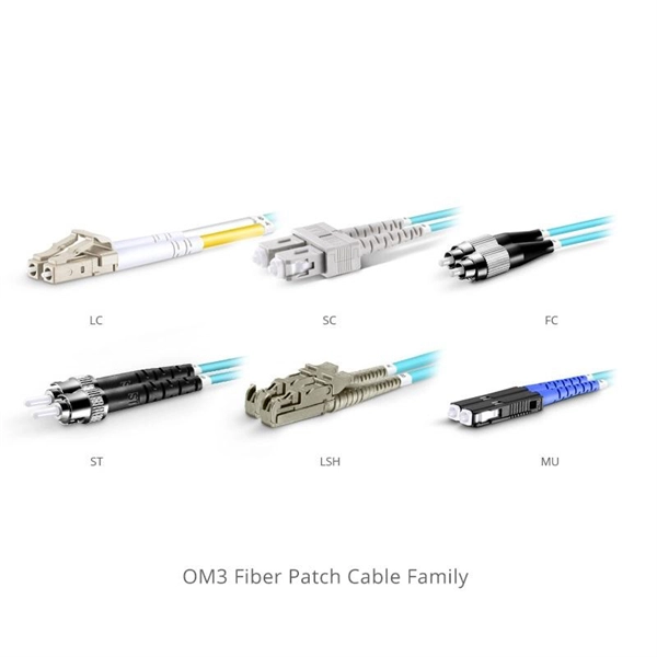
Use two fibers: one dedicated to TX, the other to RX. Both sides transmit and receive at the same wavelength (common values: 850 nm MM, 1310 nm/1550 nm SM). The front panel is usually labeled TX and RX, and you cross-connect TX→RX, RX→TX with a duplex patch cord. Switch optical port intercommunication means that the optical fiber ports of two switches are connected to each other to achieve the purpose of network connection. The connection between two or more Ethernet switches in a certain way (Uplink port, etc. ) is called the cascade. SFP modules insert into these slots and and require two strands of fiber, typically duplex Using multi mode fiber (for runs under 1000 feet) or duplex single mode fiber (for runs over 1000 feet). This is a cost-effective and high performance way to connect network switches. Use one fiber strand for both. The switch supports 10 Mbps, 100 Mbps, and 1000 Mbps connections. Using Gigabit Ethernet (1000 Mbps), the switch sends files across the network at speeds up of to 2000 Mbps due to the full-duplex nature of Gigabit Ethernet connections. You can either connect 24 Ethernet copper cables or 22 copper. Port types are limited to two: optical and Ethernet. Optical ports on switches typically accommodate optical modules for transmitting data via fiber optic cables. In situations where there's a shortage of Ethernet ports, some users may insert Ethernet port modules into optical ports to connect with.
[PDF]
A switch must use optical or copper modules that have been certified for use on Huawei switches. Non-certified optical or copper modules cannot ensure transmission reliability and may affect service stability. Huawei is not liable for any problem caused by the use of non-certified optical or copper. The purchased products, services and features are stipulated by the contract made between Huawei and the customer. Unless otherwise specified in the contract, all. Compatible SFP transceiver supports up to 80km link lengths over single-mode fiber (SMF) using a wavelength of 1550nm via an LC connector. Each SFP transceiver module is individually tested to be used on a series of Cisco switches, routers, servers, network interface card (NICs) etc. It has minimum guaranteed optical budget of 25 dB, with in most cases is enough to reach about 40 km distance. However, distance is. We supply professional-grade optical networking components for ISPs, enterprises, data centers, and network installers across Kenya, and the Authentic Huawei 155M-1310nm-15km-SM-eSFP is a proven and trusted solution for reliable fiber connectivity. Huawei is globally recognized for its advanced. Introducing the Huawei OSC015B01, a cutting-edge optical transceiver designed for high efficiency and unparalleled performance. This eSFP module, with its Tx 1310nm/Rx 1550nm wavelength capabilities, is engineered for 155M operations, making it ideal for a variety of network enhancement tasks.
[PDF]

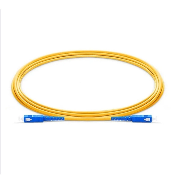
BBU end can be connected to CWDM coarse wavelength division multiplexer through CWDM color optical module and OS2 single mode optical fiber patch cord, and then transmitted to CWDM coarse wavelength division multiplexer with one or two optical fibers. The operation of base stations requires a large number of optical modules for interconnection between devices, and we will talk about the application of optical modules in mobile communication base stations. Communication base station is composed of machine room, base station, antenna, feeder. The base station can be divided into two modules: the RRU for transmitting signals and the BBU for processing signals. The BBU is small and exquisite, with low power consumption, while the RRU is large and has high power consumption. In 4G networks, the optical modules used to connect BBU and RRU are mainly gigabit to 10Gbit optical modules. In modern server racks, the wrong optical choice can silently tax performance: queues grow, link training becomes flaky, and operators end up swapping modules mid-quarter. In 5G networks, CPRI is also upgraded to eCPRI. Currently, 5G of the bearer network mainly uses 25Gbps optical.
[PDF]

The SFP port is a built-in optical port of a Gigabit Ethernet switch, so it cannot be directly connected with a twisted pair or a jumper. It needs to be connected to an optical module first, and then it can be transmitted with an optical fiber patch cord. This chapter describes how to configure Gigabit Ethernet switching on the Catalyst enterprise LAN switches. Note For complete syntax and. Si ce produit est vendu au Canada, vous pouvez accéder à ce document en français canadien à https://www. com/support/download/. The RJ45 port is for copper cable. al installation guidelines and recommended procedures. To deploy this switch effectively and ensure trouble-free operation it is recommended to first read the relevant sections in this guide so rk administ tors and support personnel that install, e is based h relevant specif tions and. This command is configured in layer-2 interface configuration mode. The optical interface speed is fixed. The optical/electric port cannot support the gigabit and full-duplex at the same time. The ordinary TX port does not. The guidelines for configuring speed on QFX5100-48T switch are as follows: If the speed on the switch is set to 10-Gbps or auto, the switch advertises all the speeds. If you have configured the speed to 100 Mbps.
[PDF]

Arduino-Powered Data Transmission with Fiber Optics Welcome to our video tutorial on optical communication with Arduino, designed to be easy t. more. They consist of a transmitter on one end of a fiber and a receiver on the other end. Most systems use a "transceiver" which includes both transmission and. I'm going to use HFBR 1414 fiber optic transmitter module which is manufactured by Broadcom. It is a low-cost high-power transmitter that is designed for use in industrial power generation, power distribution, medical transportation and gaming applications. Internally, the optical fiber consists of a highly reflective central core, which acts like a light guide. Media converters are special fiber optic transceivers used to convert from one type of cable (the media) to another, typically from copper cables to fiber optics, although some media converters will convert from one fiber type to another, e. multimode to singlemode. The FOA Guide has a page about. A fiber optic transceiver (also called an optical transceiver) is a compact module that both transmits and receives data signals through optical fibers. It serves a dual purpose — transmitting electrical signals as light pulses and receiving light pulses to convert them back into electrical form.
[PDF]
Double jacket fiber optic cable is usually the right choice when a route faces outdoor exposure, building-entry transition, direct-burial risk, rodent pressure, or higher mechanical abuse than a standard indoor cable can handle comfortably. Outdoor fiber optic cable plays a critical role in connecting buildings, deploying security and access control electronics, extending networks across campuses, supporting broadband deployments and enabling reliable communication in harsh environments. The key is that “double jacket” is not a universal premium. Fiber optic cables are the backbone of modern communication systems, offering exceptional speed, bandwidth, and resistance to electromagnetic interference. Designed to survive decades of UV exposure, temperature swings, moisture, mechanical stress, and rodent attacks, these. Fiber optic cables are specialized cables that use light to transmit data at incredibly high speeds. Unlike traditional copper cables, fiber optics is immune to electromagnetic interference, offers higher bandwidth, and allows for more reliable, long-distance connections. These cables are widely. Plan your outdoor fiber installation carefully by surveying the site, choosing the right cable type, and following FOA and OSP standards to ensure reliability. Select the best installation method—direct burial, aerial, conduit, or underwater—based on your environment and future network needs.
[PDF]

This helps keep fiber optic cables safe from harm and signal problems when you put them in. Use the right lubricant. Follow the rules for tension and bend radius. Try new methods like air blowing. Use smart. Fiber optic cable is surprisingly strong, durable and pliable; however, several best practices should be followed to ensure a successful cable installation. This article explores recommendations for pulling and installing fiber optic cable. This makes sure the cable pull is smooth and safe. Use smart monitoring devices. The Future Ready Solutions Tools & Test. A duct is available from point A to point B, a pull tape is blown in, a fiber optic cable is attached to it and the cable is pulled through the duct. Sounds simple, doesn't it. Recent observations and conversations with more than a few people in the fiber optic business have indicated. Route plan to ensure the duct run maintains the minimum bend diameter of the cable. For more information and all recommendations for installation, refer to Corning Optical Communications Standard Recommended Procedure SRP 005-011, "Duct Installation of Fiber Optic Cable". more Route plan to ensure.
[PDF]

There are 48 bicolor LEDs (green/amber) for the first 48 SFP+ ports and 16 tricolor LEDs (green/amber/white) for the SFP-DD ports. The last set of LEDs pulse once in white before indicating the FC port status in green or amber. When it blinks white twice, it shows the status of the second port of the SFP-DD. The port status LEDs for the FC ports are arranged left and right to correspond to the upper and lower ports respectively in each pair. LEDs on the port side of the switch Table 1. LEDs on Cisco Catalyst 9500 Series Switches 1 Available only on switches with 10G ports. System LED Indicator System is not operational. System is operating normally. As a group or individually, the LEDs show information about the switch and about the ports Preventing Overload - Each port that provides PoE has a maximum power it can deliver. Three LEDs are used on each port. Ports on the Cisco Catalyst switch do not have LEDs. Not the question you're searching for? Each. Number of LEDs per port - Ports that cannot be split; for example, 1G ports must have 1 LED per port. Location - A port LED should be placed right above the.
[PDF]
A fiber router includes an actual port for this connection, so you won't need an adapter that translates Ethernet into fiber optic signals or vice versa. It should be a truly plug-and-play experience, so long as you have a fiber optic modem and the accompanying service plan. Fiber internet transmits data using light signals through fiber-optic cables, which differs from traditional DSL or cable internet. Instead of a modem, fiber connections require an Optical Network Terminal (ONT), a device that converts fiber signals into an Ethernet connection. Most fiber ISPs. Which either needs a fiber optic port, or an SFP port, plus a fiber otpic-to-sfp tranceiver. Given that, how come 95% of the 5G, 1Gb/s routers I see in stores still only have ethernet ports? Rather than moving to fiber or SFP ports, consumer industry decided to go with NBASET running 2. Here's what you need to know: A fiber router, or fiber optic router, is a router that is specifically equipped. Fiber vs. Cable Internet: Here's a modem connected to a service line and a Wi-Fi router's WAN port. A cable modem generally includes a service port (for the coax line) and one or more RJ45 network ports to connect to a router. 1 with its multi-Gigabit capability is the. The good news is that once you're set up with an ONT, you're good to go for the future—you can simply plug any wireless router you like into its Ethernet port to set up a wireless fiber home network.
[PDF]

How to Use Optical Power Meter TR-504 | Optical Power Meter Working| Testing OPM, VFL, RJ45 | TRICOM In this video, we walk you through how to use the TRICOM TR-504 Optical Power Meter and explain how it works. Learn how to test fiber optic cables, OPM, VFL . Optical power meters are a key element in the optimization and maintenance of such optical networks and of their components. In this article, learn: What is an optical power meter? An optical power meter (OPM) measures the power levels of light signals in devices that transmit data or power using. An optical power meter measures the strength of light traveling through a fiber optic cable, giving you a reading in dBm (decibels relative to one milliwatt). The basic process is straightforward: turn the meter on, set it to the correct wavelength, clean your connectors, plug in, and read the. OPM interface: insert the fiber to be tested, test the optical power. An optical power meter is a tool that measures the number of optical power in a cable is fiber-optic. It helps engineers verify the performance of optical fiber systems, ensuring that the signal strength meets requirements, and is an essential tool for communication network maintenance and troubleshooting.
[PDF]

Are SFP modules universal? No — and using the wrong one can lead to errors or no connection at all. But with the right information and a trusted supplier, you can avoid compatibility issues and save money. Q1: Can I use a third-party SFP module in my Cisco switch?. SFP (Small Form-factor Pluggable) is a compact, hot-pluggable network interface module used to connect network devices (switches, routers, firewalls) to fiber optic or copper cables. It helps your device connect to a fibre optic or copper cable — like a SIM card for your phone, but for your network. SFPs are used for different network types and speeds. Switch optical modules, which convert electrical signals to optical signals and vice – versa, and optical interfaces, which serve as the physical connection points, play a pivotal role in determining the speed, distance, and reliability of data transmission. Transceiver compatibility is a key concern in enterprise network deployments. Can an SFP. Every network engineer runs into it: the optical transceiver that should work, but doesn't. First, there's form factor—the SFP you used last year won't fit the QSFP-DD ports your new switches need. Then protocols and speeds complicate things. An optic that handles Ethernet might fail entirely on a.
[PDF]

This article provides a detailed technical comparison between fiber optic and copper cables, offering a clear perspective for engineers, network architects, and procurement managers. The core distinction between the two technologies lies in the physics of data. There are significant differences in performance between ADSS cables (all-dielectric self-supporting optical cables) and traditional optical cables, which are mainly reflected in the following aspects: 1. This type of fiber optic cable is designed to support its own weight without the need for additional support structures like messenger wires. The ADSS. There are several factors to assess when deciding which cable type is right for your application, including speed of connection for new customers, ease of changes and repairs, installer certification requirements, and the ability to expand the network over time. ADSS Fiber Optic Cables are a type of optical fiber cable designed specifically for. All-dielectric self-supporting (ADSS) cable is a type of optical fiber cable that is strong enough to support itself between structures without using conductive metal elements. It is used by electrical utility companies as a communications medium, installed along existing overhead transmission.
[PDF]

The optical module is usually composed of Transmitter Optical Subassembly (TOSA, containing a laser LD Chip), Receiver Optical Subassembly (ROSA, containing a photodetector PD Chip), a driving circuit, and an optical and electrical interface. Its schematic is shown in. This section explains the structure of a typical pigtail butterfly module, which gets its name from the two rows of seven leads at right angles on each side of the metal package plus an optical fiber pigtail at one end (Fig. Let's look at the internal structure (Fig. 2) of a common butterfly. Optical modules are devices used to connect network devices, transmit and receive data between network devices, and can be used to convert optical and electrical signals. The optical module is a very important component in an optical communication system. Optical devices are the core components of optical modules. TOSA and ROSA in Common Optical Transceiver Modules For ordinary optical transceiver modules, there are two optical devices, TOSA and ROSA, which have opposite effects.
[PDF]

With protective doors, dust-proof 2). Suitable for many types of modules, used in cabling work area subsystem 3). Embedded type surface, easy for installation and removal 4). Available for fiber optic SC simplex or LC duplex and can be used in both surface mounted. 1). This termination box supports 0. 0mm pigtails and 2x3mm indoor drop cables. Discover the Welink FTB-1005: a high-quality 1 Core Fiber Optic Outlet for FTTH. RoHS certified, compact, durable, and easy to install. Compact Design: Space-saving footprint (86x86mm) ideal for residential and office wall mounting. Splice Protection: Integrated tray securely holds fusion. FTTH Terminal box is a compact fiber terminal for use at the final fiber termination point in the customer premises. It provides mechanical protection and managed fiber control in an attractive format suitable for use inside customer premises, A variety of possible fiber termination techniques are. 1 Core Fiber Optic Desk Terminal Box for SC, FC Adapter, Patch Cord or Pigtail Description: 1). It provides a secure and convenient location for fiber optic splicing, connecting the drop cable and the passive optical equipment of the optical network. protection and management for the FTTx network building. Features: Scope of application 3. Specification: Applications: 1 Core Fiber Optic Terminal Box is used as a termination point for the feeder cable to connect with drop cable in FTTx communication network.
[PDF]