Cable Trays* — Max two 24 in. (610 mm) wide by max 6 in. (151 mm) deep open-ladder cable tray with channel-shaped side rails formed of 0. 54 mm) thick aluminum or min 0. In practice, cable tray dimensions are a system of interrelated measurements —width, depth, length, and material thickness—that directly affect cable fill compliance, heat dissipation, structural loading, and long-term expandability. From an engineering standpoint, cable tray dimensions are not. Perforated Cable Tray System expertly constructed from high-grade stainless steel, offering exceptional durability and resistance to corrosion. With side height 100mm. A properly designed and installed cable tray system will provide. Studs — Wall framing to consist of wood studs or channel shaped steel studs. Wood studs to consist of nom 2 by 4 in. Additional studs shall be used to completely frame. Best Size: Here, deep trays (75mm to 150mm) are used since power cables are typically thick and heavy. Data cables, such as your Wi-Fi or computer ones, are extremely sensitive. They do not get hot; however, they do not like to hang or sag. In case a data cable folds in an excessive manner, the. ect the minimum bend ra-dius for cables as they exit the bottom of the cable tray. A rung spacing of 6 to 9 inches (150 to 230 mm) is preferable when the cable tray cont d for instrumentation and control applications that require additional protec eferred to support and protect numerous small.
[PDF]
Proper planning for installing cable tray includes calculations based on loading, support systems, cable/wire fill and spacing, conductor types, securing of the cables and wire, and proper grounding and bonding are all important aspects of cable tray installation. How about organizing your wiring with a cable tray system? Smart move. Whether you're building a commercial setup or upgrading an industrial plant, proper cable tray installation ensures neat wiring, safe access, and easy maintenance. This guide covers the critical steps, from selecting the right electrical cable tray and performing accurate cable fill. Cable tray installation implies the construction of an electric road that will be safe. In order to get it right, installers are supposed to adhere to a plan that ensures that wires are kept cool and the building is stable. The beginning of success is to review the Bill of Quantities (BOQ) so that. Our solutions and products are made in the USA and our service and support can assist with any install or product selection questions that you may have. Here's what you'll learn: Planning: Assess cable requirements, calculate loads, and select the right tray system (ladder, trough, or wire mesh) based on factors like weight and environment. Proper installation of cables in trays is critical for maintaining an efficient and safe electrical system. This is why proper planning and execution are.
[PDF]

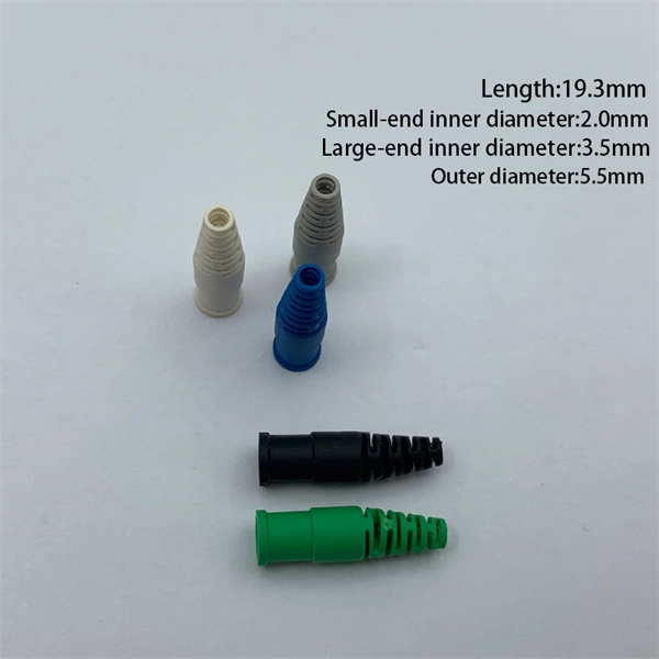
How to hardwire a Self-Regulating heat cable into a junction box, with a tutorial of the final end seal. First thing, get the sealing ring and connect it onto the connector body. Make sure it gets onto the very e. Safety comes first, and clear info makes it doable. Know Your. We'll show you how to size the heater, run a new, safe 240-volt circuit and install a programmable thermostat. Most homes have sufficient capacity for the new circuit in the service. If you're working with heating cables, understanding how to connect them safely and efficiently is crucial. In this guide, we'll break down the steps in simple terms. Whether you're a DIY enthusiast or a professional, this article is here to help. Stay safe and ensure proper installation with these. I need help wiring an electric furnace with heat elements. I ran number 6 wire with ground from my 100 amp service box where I installed a 60amp double pole breaker. The furnace comes with an other set of breakers one 60amp and one. A distribution board or distribution box is where the main power supply is distributed to multiple loads. Single Phase Distribution Box generally consists of Double Pole MCBs, Single Pole MCBs, and RCCBs.
[PDF]
The Box Fill Calculator is an essential electrical installation tool that determines the maximum number of conductors, devices, and fittings that can be safely installed in electrical boxes according to National Electrical Code (NEC) standards. Calculate electrical box fill capacity and ensure NEC compliance for proper wire management and electrical safety. Click on any. Learn how to wire a distribution box step by step! This video shows real on-site footage of electrical installation, demonstrating safe and standardized wiring methods used by professionals. It serves as a central hub for distributing electricity throughout a building, ensuring that power is delivered safely and efficiently to all the required locations. The National Electrical Code (NEC) and Canadian Electrical Code (CEC) specify strict limits on how. In just a few steps you will find the wiring and assembly plan, including complete documentation in accordance with standards. This is the design philosophy which the browser-based distribution board configurator from Eaton is based on. Distribution board configurator for different types of. Hey, in this article we are going to see the Single Phase Distribution Box Wiring Diagram and Connection Procedure. And all the switching and protective devices are installed in the.
[PDF]

This video shows real on-site footage of electrical installation, demonstrating safe and standardized wiring methods used by professionals. Whether you are setting up a new telephone line or troubleshooting an existing one, understanding the basics of wiring is essential. In this article, we will explore the key components of a telephone line box and the. In this video, we'll walk you through the process of wiring a home distribution box with a detailed connection diagram. What is Distribution Board? Distribution board. mounted in OnQ Service Center Enclosures and come in several different telecom/video combinations; an example (6+8) is shown yle fittings for connecting incoming and outgoing cables. ve an 8 position 110 punch-down connector for incoming 4 ine service and 110 (8) position punch-down connectors. With the right wiring diagram, you can easily complete the job and get your outside phone box up and running in no time. If you're looking for a wiring diagram to help you install an outside phone box, then you've come to the right place. From there, the wiring is divided into separate lines for different areas of the house, such as bedrooms, living rooms, and kitchens. Each line is then connected to a.
[PDF]

This video shows real on-site footage of electrical installation, demonstrating safe and standardized wiring methods used by professionals. more Learn how to wire a distribution box step by step! This video shows real on-site footage of. Connecting a distribution box involves several steps to ensure proper electrical flow. Follow this guide for a clear and safe connection process: Before starting, always ensure the main power is turned off to avoid electrical shock. Fix the box securely to the wall, ensuring it's at an accessible. An electrical panel box, also known as a breaker box or a distribution board, is a crucial component of any electrical system. It serves as a central hub for distributing electricity throughout a building, ensuring that power is delivered safely and efficiently to all the required locations. In this guide, we'll break down everything you need to know to install a distribution box correctly and confidently. Choose the right box based on environment (indoor/outdoor), load capacity, and durability. Check for proper IP/NEMA ratings and material quality. Whether you're an electrician or a DIY enthusiast, this guide will help you understand the basics of home electrical distribution. Material preparation: Prepare the required circuit breakers, wires, wiring ties and other materials, and ensure that they meet the design drawings and installation requirements. Location determination:.
[PDF]

Learn how to install a distribution box safely and correctly. Covers wiring, placement, standards, and expert tips for a compliant setup. It takes the incoming power and safely distributes it to different. In this video, we'll walk you through the process of wiring a home distribution box with a detailed connection diagram. more Welcome to our channel! In this video. Whether you are an electrical contractor or a construction brigade, knowing how to properly and safely install distribution boxes is the basis of ensuring the safe operation of the entire system. It serves as a central hub for distributing electricity throughout a building, ensuring that power is delivered safely and efficiently to all the required locations. In modern electrical systems, cable distribution boxes (also known as electrical distribution boxes or distribution boxes) play a crucial role as the key hub for managing, distributing, and protecting circuits. Whether it is residential buildings, commercial facilities or industrial sites, the. In this guide, we will break down the key elements involved in connecting the main power supply to your home, providing a clear path for a successful setup. We will focus on the critical parts of the system, from basic components to step-by-step assembly procedures. Whether you are looking to.
[PDF]

This video shows real on-site footage of electrical installation, demonstrating safe and standardized wiring methods used by professionals. more Learn how to wire a distribution box step by step! This video shows real on-site footage of. Understanding the wiring diagram of an electrical panel box is essential for electricians and homeowners alike, as it allows them to troubleshoot any electrical issues, carry out repairs, or make additions to the system. The electrical panel box wiring diagram provides a visual representation of. A distribution box, also known as an electrical distribution board, is a critical component in electrical systems. It serves as a central point for distributing electricity to various circuits in a building or facility. This section will explain its function, types, and the importance of correct. Understanding how to safely set up the main connections of a home's power distribution system is essential for ensuring reliable and secure operation. A correct installation process minimizes the risk of electrical faults and increases the longevity of your setup. Proper knowledge is crucial for. Material preparation: Prepare the required circuit breakers, wires, wiring ties and other materials, and ensure that they meet the design drawings and installation requirements. Whether you're an electrician or a DIY enthusiast, this guide will help you understand the basics of home electrical distribution. What is Distribution Board? Distribution board.
[PDF]
In this video, we'll walk you through the process of wiring a home distribution box with a detailed connection diagram. Whether you're an electrician or a DIY enthusiast, this guide will help you understand the basics of home electrical distribution. more Welcome to. This guide provides step-by-step instructions for connecting a distribution box and highlights key factors to consider during installation. What Is a Distribution Box? A distribution box, also known as an electrical distribution board, is a critical component in electrical systems. A distribution board or distribution box is where the main power supply is distributed to multiple loads. In this article, I'll teach you how to wire a Power Distribution Block (PDB) to distribute electricity from a single input source to multiple pieces of equipment in your branch circuit.
[PDF]

Learn how to safely wire a single-pole (one way) light switch in this beginner-friendly tutorial. Whether you're replacing an old switch or doing your first DIY electrical project, this guide will walk you through every step — no experience needed!. more. This page contains wiring diagrams for household light switches and includes: a switch loop, single-pole switches, light dimmer, and a few choices for wiring an outlet/switch combo device. That's because virtually all light switches that control 120-volt fixtures are single-pole switches. Most light switches are also single-throw, which. Summary: Fully explained wiring diagrams and photos show how to wire switches including: single switches, 3-way switches, 4-way switches, and dimmer switches. and Be Sure to Subscribe! Make sure the circuit power has been turned off, and mark the circuit breaker or fuse to indicate that work is. A distribution board or distribution box is where the main power supply is distributed to multiple loads. And all the switching and protective devices are installed in the distribution box. Single Phase Distribution Box generally consists of Double Pole MCBs, Single Pole MCBs, and RCCBs. Wiring a single light switch may seem like a daunting task, but with the right tools, a bit of patience, and this comprehensive guide, you'll be able to tackle this DIY project with confidence. Remember, while this guide provides detailed instructions, always prioritize safety and consult a.
[PDF]
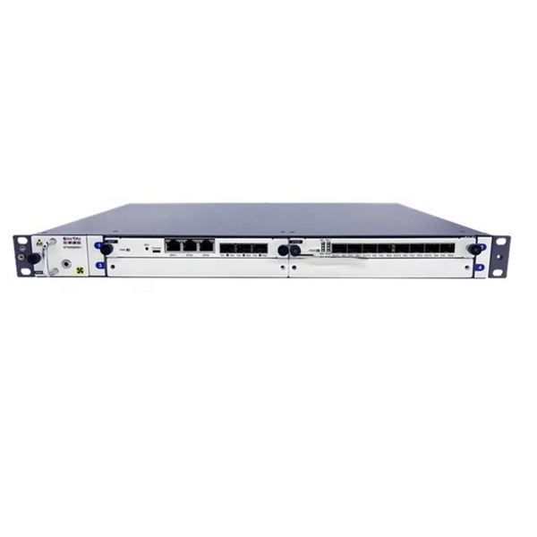
This beginner-friendly guide will walk you through the step-by-step process of fiber optic cable installation for each method, highlighting best practices, tools, and considerations. Proper connection of fiber optic cables is essential to harness these benefits fully, as even minor errors can lead to significant performance issues like signal loss. This article will guide you through the necessary tools, materials, and methods on how to connect fiber optic cables effectively. Starting with site surveys and permissions, to installing fiber optic cable and emphasizing the process as a key stage in mastering fiber optic installation, to the careful handling of cables and high-stakes splicing, each stage is critical. Discover the exact steps, adhere to stringent safety. Single family homes, apartments, condominiums and other multi-dwelling units are increasingly wired with fiber optic cable to future-proof installations and create more reliable, higher-bandwidth and faster speed network and video infrastructures. The processes. Running fiber internally involves extending this high-speed link from the service entry point to a centralized location, such as a dedicated media closet or network rack. This DIY effort is undertaken to maximize performance, improve aesthetics, or relocate the Optical Network Terminal (ONT) to a.
[PDF]
Welcome to our channel @Electricalgenius In this video, we'll take you through a detailed step-by-step guide on wiring a home distribution DB (Distribution Board) box. A distribution box, also known as an electrical distribution board, is a critical component in electrical systems. It serves as a central point for distributing electricity to various circuits in a building or facility. Whether you're an electrician or a DIY enthusiast, this tutorial will help you understand the fundamentals of wiring a. Distribution Board or DB is an electricity supply system or a common enclosure that distributes the electrical power feed into subcircuits. Whether in a home or an industrial facility, this box keeps your electrical setup organized, functional, and efficient. However, the key to. Circuit breaker wiring configurations involve organizing main switches, busbars, and branch breakers within a distribution box. Common configurations include single-phase for homes and three-phase for.
[PDF]

This handbook covers the code of practice in protection circuitry including standard lead and device numbers, mode of connections at terminal strips, colour codes in multicore cables, dos and donts in execution. Also principles of various protective relays and schemes including special protection. Relay systems protect high-voltage equipment and transmission lines to ensure safe, stable systems. Ensuring that. lectrical work practices. See NFPA 70E in the USA, e conduit nut provi ource termination point. * NOTE: When connecting the control side of this device (#18 wires) to power line circuits, provide curre. 1/3HP@120V. The testing and verification of relay protection devices can be divided into four groups: Type tests are needed to prove that a protection relay meets the claimed specification and follows all relevant standards. Since the basic function of a protection relay is to correctly function under abnormal. Manual intended for personnel responsible for installing, commissioning and using VIP protection 400. The handbook for protection engineers includes guidelines on protective circuitry, protective relay principles, and testing procedures for switchgear and relays. It covers standard codes, wiring practices, and norms for protecting generators, transformers, and lines, and provides detailed.
[PDF]

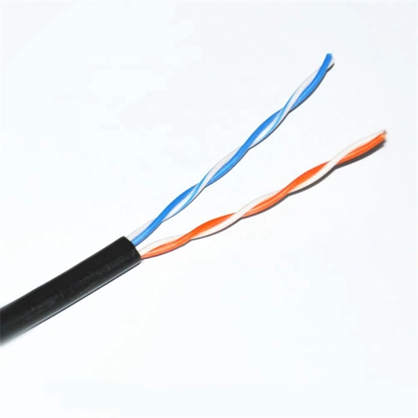
The maximum distance of copper is around 328 feet (100 meters), which is a far shorter range than is offered by either of the fiber optic cable types. This is because fiber optic cable is not affected by attenuation, dispersion, or EMI in the same way that copper is. Many factors decide the fiber cable distance, but the key factors include the below six aspects. Attenuation First is the attenuation of the optical fiber. For some. Fiber optic cable transmission distance is determined by two primary physical factors that affect signal quality as light travels through the fiber medium. The selection of fiber optic cables over copper wires or vice versa depends on factors such as bandwidth, distance, and cost of transmission. Fiber optic cables transmit data using light waves, enabling higher. Fiber optic cables have revolutionized modern communication networks by enabling blazing-fast data transmission across vast distances. However, fiber cable runs are not limitless. However, fiber optic cable performance. Q: Is there and electromagnetic interference with optic cables? A: The fiber is glass and the cable is plastic, neither of which are affected by electromagnetic interference. There is a cable used in electrical transmission lines called OPGW- optical power ground wire - that has fiber inside a wire.
[PDF]

In this tutorial, I will show you how you can connect the Optocoupler to Arduino, read the data as Analog or Digital, and if necessary convert the analog values to digital, and how to reduce noise from the sensor. The Infrared Slotted Optical Optocoupler Module is a device that uses infrared light to transmit signals between two electrically isolated circuits. It consists of an infrared emitter (LED) and a photodetector (phototransistor) housed in a slotted enclosure. When an object passes through the slot. Slotted Optocouplers (Photo Interrupters) are very useful sensors, often included in Arduino projects to detect position of moving objects, measure speed of rotation, or linear motion, frequency of events, and many others. They are easy to use, but it is important to understand how they work, so. This tutorial is a comprehensive, practical guide to the Speed Sensor / Tacho Sensor (Slot-Type Optocoupler) (Leobot Product #245). Moreover, a simple application is programmed that shows how to wire and how to program an Arduino when working with the module. In this tutorial, the module is used as an “digital input board”. If you want to use the. In this project, I will talk about Phototransistor Optical Interrupter Switches (Opto Coupler) Module, how this module works and helps in determining the speed of a rotating object and finally I will show you how to Interface Optical Interrupter Switch Sensor with Arduino and measure the speed of a.
[PDF]