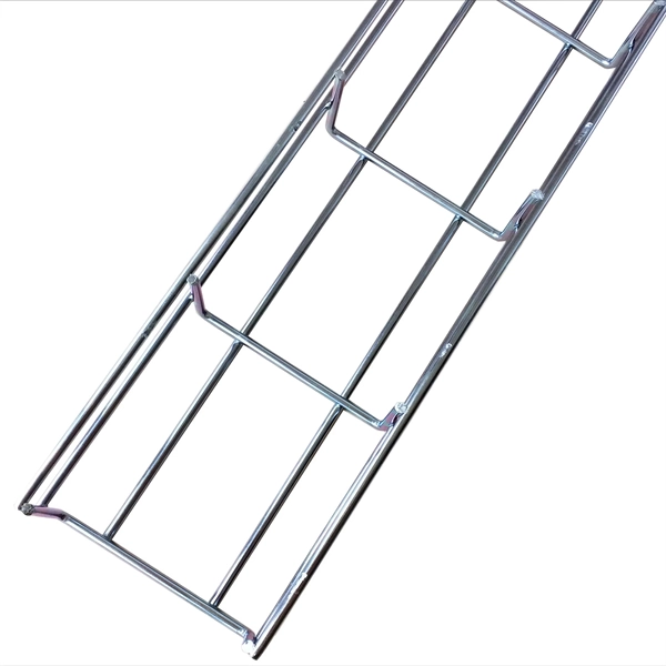
Cable Trays* — Max two 24 in. (610 mm) wide by max 6 in. (151 mm) deep open-ladder cable tray with channel-shaped side rails formed of 0. 54 mm) thick aluminum or min 0. In practice, cable tray dimensions are a system of interrelated measurements —width, depth, length, and material thickness—that directly affect cable fill compliance, heat dissipation, structural loading, and long-term expandability. From an engineering standpoint, cable tray dimensions are not. Perforated Cable Tray System expertly constructed from high-grade stainless steel, offering exceptional durability and resistance to corrosion. With side height 100mm. A properly designed and installed cable tray system will provide. Studs — Wall framing to consist of wood studs or channel shaped steel studs. Wood studs to consist of nom 2 by 4 in. Additional studs shall be used to completely frame. Best Size: Here, deep trays (75mm to 150mm) are used since power cables are typically thick and heavy. Data cables, such as your Wi-Fi or computer ones, are extremely sensitive. They do not get hot; however, they do not like to hang or sag. In case a data cable folds in an excessive manner, the. ect the minimum bend ra-dius for cables as they exit the bottom of the cable tray. A rung spacing of 6 to 9 inches (150 to 230 mm) is preferable when the cable tray cont d for instrumentation and control applications that require additional protec eferred to support and protect numerous small.
[PDF]
Reach inside panels, disconnects, and raceway to bend and position heavy duty cable with greater precision and less fatigue than bending by hand. The dies on the ends of these benders are sized to handle large wire gauges; fit your cable into the dies and push or pull the handle to bend. Smooth. Check each product page for other buying options. Need help? Online shopping for Tools & Home Improvement from a great selection of Wall Plates & Accessories, Breakers, Load Centers & Fuses, Electric Motors, Testers & more at everyday low prices. Start your sales inquiry online and an expert will connect with you. Easily find the nearest Schneider Electric distributor in your location. Find support resources for all your needs, in one place. Discover our range of products in Terminal blocks, protectors and. Buy a wholesale switchgear bending plate and experience smooth management and distribution of electricity. Mounting hardware is available as an add-on to any branch circuit power whip cable assembly. PDU Cables offers a variety of options that facilitate elevated mounting positions including beam and pedestal clamps, mounting bolts, brackets and mounting ears attached through the backs of boxes. NVent Hoffman BMP4080 Power Distribution Mounting Plate, Mild Steel, Use With Terminal Boxes, 14. 08 inches thick and is.
[PDF]
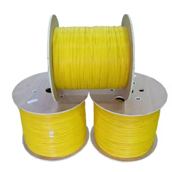
The normal recommendation for fiber optic cable is the minimum bend radius under tension during pulling is 20 times the diameter of the cable (d). This includes pulling tension, minimum bend radius or diameter and crush loads. Installers must understand these specifications and know how to install cables without. Fiber optic cable bend radius is a critical mechanical parameter that determines how sharply a cable can be bent without risking microbending, macrobending, signal loss, or long-term structural fatigue. It is measured from the inside of the bend, not the outer curve. Fiber optic cables transmit data through light propagation within a glass core. The correct bend radius calculation is a fundamental prerequisite for high-quality fiber optic installations and is decisive for long-term network performance and reliability. While installers are aware of the fundamental importance of minimum bend radii, they often lack the practical know-how to. The bend radius of fiber cables is critical for maintaining high performance and longevity. This overview explains key standards, installation best practices, and consequences of exceeding limits during handling, routing, and management. What Is Bend Radius? You need to understand the concept.
[PDF]
The normal recommendation for fiber optic cable is the minimum bend radius under tension during pulling is 20 times the diameter of the cable (d). This includes pulling tension, minimum bend radius or diameter and crush loads. Installers must understand these specifications and know how to install cables without. Fiber optic cable bend radius is a critical mechanical parameter that determines how sharply a cable can be bent without risking microbending, macrobending, signal loss, or long-term structural fatigue. Proper bend radius control ensures the integrity of optical performance and protects the glass. Fiber optic cables have revolutionized communication networks, providing extremely fast data transmission through pulses of light traveling along thin glass fibers. However, these slim cables often need to twist and turn during infrastructure builds and maintenance. So an important question arises:. Ignoring the minimum bend radius for fiber optic cable can result in signal loss, increased attenuation, and long-term reliability issues. Have a network installation project? What's The Bend Radius of Fiber Optic Cables? The bend radius of fiber cables. Always keep the fiber optic cable bend radius at least 20 times the cable diameter during installation and 10 times after installation to prevent damage and signal loss. Use bend-insensitive fiber optic cables in tight spaces to reduce signal loss and allow sharper bends, but still follow.
[PDF]
A KVM switch (with KVM being an abbreviation for "keyboard, video, and mouse") is a hardware device that allows a user to control multiple computers from one or more sets of keyboards, video monitors, and mouse. NameSwitches to connect multiple computers to one or more peripherals have had multiple names. The earliest name was. USB keyboards, mice, and I/O devices are the most common devices connected to a KVM switch. The classes of KVM switches discussed below are based on different types of core technologies, which vary in how the KV. A KVM Switch is a hardware device used in that allows the control of multiple computers from a single keyboard, monitor and mouse (KVM). The switch allows data center personnel to connect to any server.
[PDF]
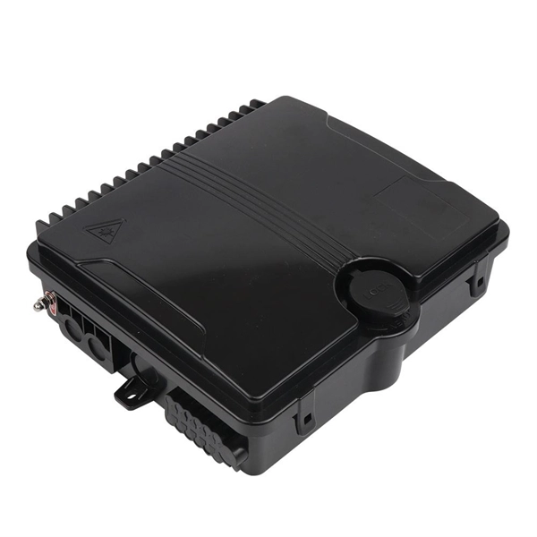
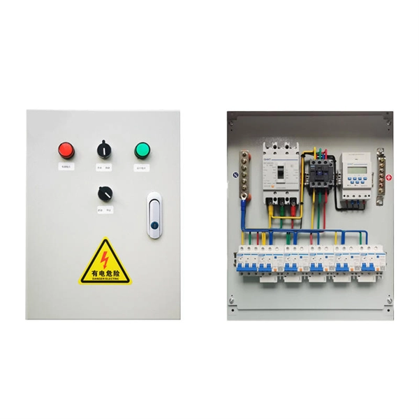
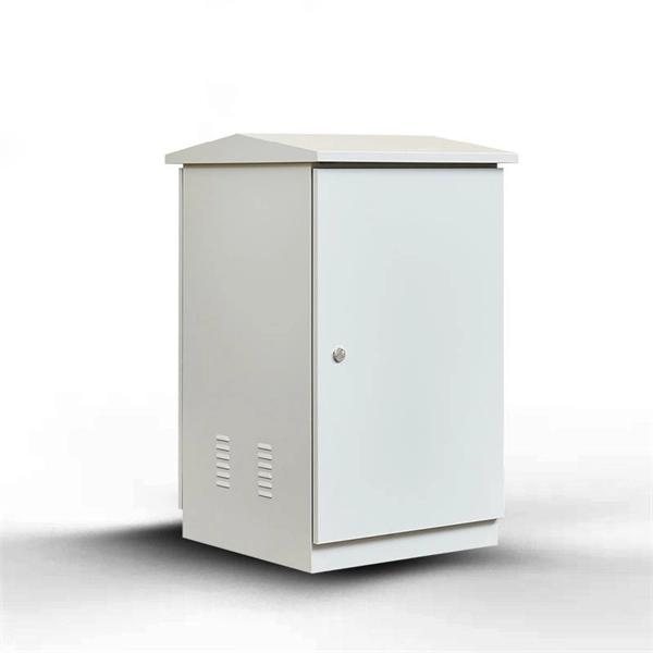
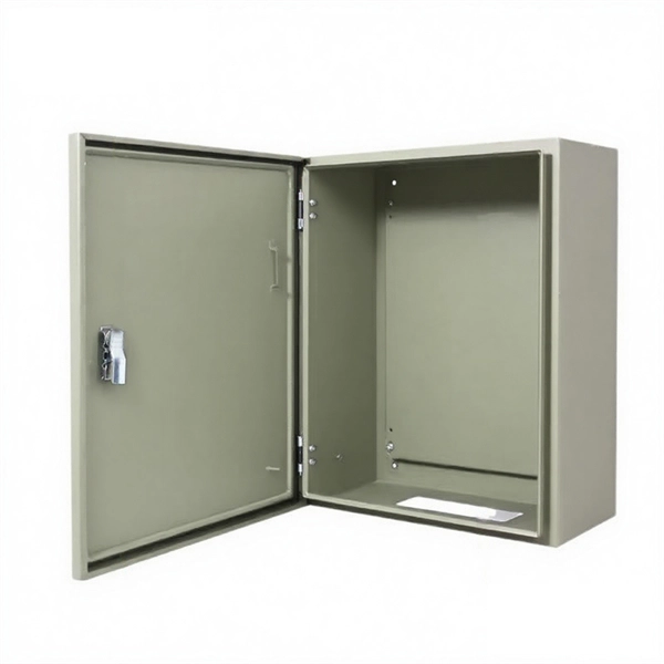
Users often find key cabinets inside, such as incoming line, outgoing line, and capacitor compensation cabinets. Main internal parts include circuit breakers and protection devices. Low voltage distribution boxes manage and distribute electrical energy safely, ensuring easy. The internal structure of the distribution box is designed to safely distribute power from the main power source to multiple branch circuits. It provides convenience for protection, control and maintenance. This article discusses the construction of the distribution box, its functional divisions. A distribution box is a key part of electrical systems in buildings. It helps control and distribute electricity to different areas. Contact for purchase: WhatsApp +8615858778282. more This video details the design standards of this red construction. The three-level distribution system refers to a system that distributes electric power through three levels of distribution devices from the incoming power line at the construction site to the electrical equipment. This panel acts as the heart of an electrical network. It ensures that circuits are safe, organized, and easy to manage. This device supplies power to end-user devices and ensures safe, easy access at the point of use. The low voltage distribution box controls, protects, and.
[PDF]

This standard covers the construction, mechanical, electrical, and optical performance, installation guidelines, acceptance criteria, test requirements, environmental considerations, and accessories for a nonmetallic, all-dielectric self-supporting (ADSS) fiber optic cable. An All-Dielectric Self-Supporting (ADSS) cable operates without metallic messengers, relying entirely on its aramid yarn strength members. For a typical 12-fiber ADSS cable with a 8. AFL-ADSS® (All-Dielectric Self-Supporting) cable is ideal for installation in distribution as well as transmission environments. This guide provides general recommendations for the selection of methods, equipment, and tools for the stringing of ADSS (All Dielectric Self-upporting) fiber optic cables including short and Long Span ADSS cables. The installation methods for ADSS cables are essentially the same as those used for. This Installation Manual is a recommendatory installation document provided by HANGZHOU ZION COMMUNICATION CO. The installation manual is established based on the newest issued international standards such as lEEE Std 1222: 2004, "lEEE standard for all-dielectric. Round aramid reinforced ADSS cable for intermediate and long spans, 4 – 96 fibres. VDE: A- DF 2Y (ZN) 2Y This specification covers a family of optical cables with 4 - 96 fibres for intermediate and long spans.
[PDF]
The change of both physical length and strain-dependent refractive index of the fiber, are calculated by altering the bend radius of the sensor. The detection of the bend radius is determined by the shift of the Bragg wavelength from the reflection/transmission. Fiber Bragg grating (FBG) sensors have emerged as advanced tools for monitoring a wide range of physical parameters in various fields, including structural health, aerospace, biochemical, and environmental applications. This review provides a comprehensive overview of FBG sensor technology. A variation of the period of the grating inscripted in a fiber optic – induced by mechanical or thermal perturbation – causes a shift of the reflected peak wavelength, due to the related optical path length variation. where Pij are the Pockel coefficients of the elasto-optic tensor, n is the. Optical sensors based on Fiber Bragg Gratings (FBG) are becoming increasingly popular. They are easy to install, immune to electromagnetic interferences and can also be used in highly explosive atmospheres. But just how does a fiber Bragg grating work? Our experts answer this and other questions. In the field of mechanical engineering, the accurate calculation of bending strength for spur gears is fundamental to ensuring the reliability and durability of transmission systems. The basic approach involves simplifying the gear tooth as a cantilever beam and incorporating form factor and stress.
[PDF]
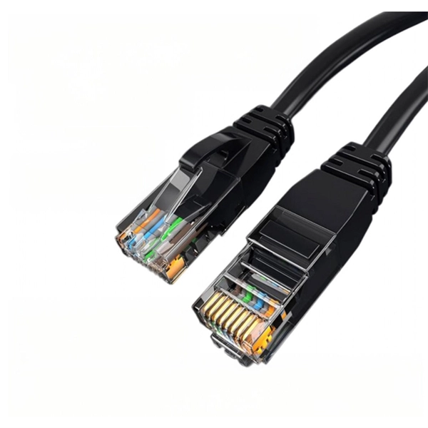
The normal recommendation for fiber optic cable is the minimum bend radius under tension during pulling is 20 times the diameter of the cable (d). While installers are aware of the fundamental importance of minimum bend radii, they often lack the practical know-how to systematically calculate bend radii under real installation conditions. Different fiber types, cable designs and load conditions each require specific bending radii calculations. This calculator helps you determine the minimum recommended bend radius for your fiber optic cable during installation and long-term use. Note: Some cables have. The calculator uses conservative routing multipliers, then compares the actual bend radius against the cable family minimum so you can spot risky turns early. Configuration type Cable family Installation phase Route style Route length (m) Used for bend density and overall planning context. Cable. To ensure optimal performance and long-term reliability, follow these industry-standard calculations: Copper Ethernet (Cat5e/Cat6/Cat6a): The standard rule of thumb is 4x the outer diameter of the cable. For shielded cables or thicker jackets, always consult the manufacturer's datasheet to prevent.
[PDF]

Fiber optic cables use total internal reflection to keep light signals bouncing within the core, allowing data to travel quickly and with minimal loss. An optical fiber is comprised of a light-carrying core in the center, surrounded by a cladding that acts to traps light in the. Optical fibers are thin glass rods that use the properties of light reflection and refraction to transmit data over long distances. They actively shuttle data encoded in pulsing light across vast distances using only subtle differences in materials. They consist of three elements as shown in Figure 1: a central core, cladding and a protective coating. Optical fibers operate on the principle of total internal reflection, which. Refraction and total internal reflection (TIR) are the two fundamental optical principles that allow light to propagate through optical fibers over long distances with minimal loss. Understanding these mechanisms is essential for designing, installing, and troubleshooting fiber networks in FTTH. Fiber optic cables use a similar concept to guide light. Fiber optic. Describe the workings and uses of fiber optics. Analyze the reason for the sparkle of diamonds. A good-quality mirror may reflect more than 90% of the light that falls on it, absorbing the rest.
[PDF]
IEC 61537 is the internationally recognized benchmark for metal cable tray systems. It applies to cable trays made of steel, stainless steel, aluminum, or other metallic materials. The standard ensures these systems can handle the physical and electrical loads they're exposed to. association representing the major electrical equipment manufac-turers in the U. The Cable Tray ng standards, performance standards, test standards and application in this document have been tested extens ompetent professional en completely installed, without damage either to conductors or. Cable trays play a vital role in supporting electrical cables and wires in commercial, industrial, and utility installations. For proper installation, design, and maintenance, adherence to international standards is essential. One of the most recognized frameworks globally is the IEC standard for. The B-Line series Cable Tray Manual was produced by our technical staff. The following pages address the 2014 National Electrical Code® requirements for cable tray systems as well as design. This publication is intended as a practical guide for the proper and safe* installation of cable ladder systems, cable tray systems, channel support systems and associated supports. These guidelines will be useful to engineers, contractors, and maintenance personnel. This is why proper planning and execution are.
[PDF]

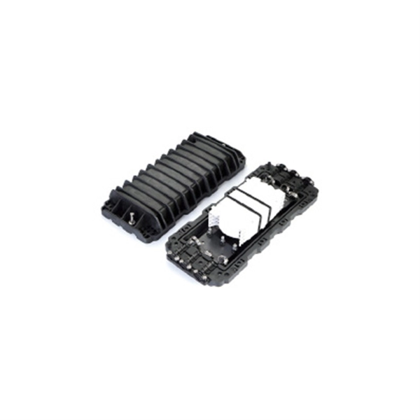
The optical module is usually composed of Transmitter Optical Subassembly (TOSA, containing a laser LD Chip), Receiver Optical Subassembly (ROSA, containing a photodetector PD Chip), a driving circuit, and an optical and electrical interface. Its schematic is shown in. This section explains the structure of a typical pigtail butterfly module, which gets its name from the two rows of seven leads at right angles on each side of the metal package plus an optical fiber pigtail at one end (Fig. Let's look at the internal structure (Fig. 2) of a common butterfly. Optical modules are devices used to connect network devices, transmit and receive data between network devices, and can be used to convert optical and electrical signals. The optical module is a very important component in an optical communication system. Optical devices are the core components of optical modules. TOSA and ROSA in Common Optical Transceiver Modules For ordinary optical transceiver modules, there are two optical devices, TOSA and ROSA, which have opposite effects.
[PDF]

In its most common form, a cube, a beam splitter is made from two triangular glass prisms which are glued together at their base using polyester, epoxy, or urethane-based adhesives. (Before these synthetic resins, natural ones were used, e. ). A beam splitter or beamsplitter is an optical device that splits a beam of light into a transmitted and a reflected beam. It is a crucial part of many optical experimental and measurement systems, such as interferometers, also finding widespread application in fibre optic telecommunications. In its. 📦 For purchasing, use the RP Photonics Buyer's Guide for beam splitters. It provides an expert-curated supplier directory, buyer-focused technical background information, and structured selection criteria to support professional procurement decisions. Light from an input fiber is first collimated, then sent through a beam splitting optic to divide it into two. The resultant output beams are then focused back into the output fibers. Note that jT j2 is the transmitted intensity. Similarly, E2 ! RE3 + T E4. The transformation matrix is then given by The elements of the beam splitter transformation matrix B are determined using the.
[PDF]
Optical fiber is used by telecommunications companies to transmit telephone signals, Internet communication and cable television signals. It is also used in other industries, including medical, defense, government, industrial and commercial. In addition to serving the purposes of telecommunications, it is used as light guides, for imaging tools, lasers, hydrophones for seismic waves, SON. OverviewFiber-optic communication is a form of for from one place to another by sending pulses of or through an. The light is a form of. First developed in the 1970s, fiber-optics have revolutionized the industry and have played a major role in the advent of the. Because of its advantages over electrical transmission, optical fiber. In 1880, and his assistant created a very early precursor to fiber-optic communications, the, at Bell's newly established in.
[PDF]
Watch as we take you through the entire manufacturing process step by st. How to Make Electrical Pigtails: This is a basic tutorial on what electrical pigtails are and how to make them. Disclaimer: Always use multiple sources and do your homework before performing any electrical work. Also, make sure all work is done within national and local code. Combining is putting the layers of linerboard and medium together to form complete corrugated board. Medium is engineered to form easily into flutes as it is fed between two large gear-like rollers on the Wet End of the corrugator. Linerboard is engineered to remain flat as it adheres to the top. A corrugated box is a packaging carton made of a fluted (wavy) inner layer sandwiched between two flat sheets of paper. The thickness of the inner and outer sheets can be customized as per a brand's needs and the nature of the product. The three-layer structure creates a box that is both strong and. Pigtails act as bridges, allowing you to connect several wires to a single point without overloading connections. Professionals often prefer this method because it isolates issues, protecting downstream circuits from cascading failures. Why does this matter? Modern systems demand precision. A. The corrugated box manufacturing process involves several stages, beginning with paper rolls and ending with finished packaging boxes ready for shipment. These paper rolls are loaded onto the.
[PDF]