Calculate lighting loads, branch circuit requirements, and illumination levels per NEC Article 210 and 220 standards. Essential tool for commercial and residential lighting system design. Calculations are for reference only. Always verify against NEC and local codes before installation. Consult a. Free electrical load calculation tool for residential and commercial buildings. Your Project's Total Power Demand This isn't just adding up wattages randomly. Think of your home as a busy kitchen—not every appliance runs at once. Proper load calculations ensure that electrical systems are safely designed with adequate capacity for present and future needs. What is Electrical Load. Calculating Circuits for Lights and Sockets in Commercial Fit-Out Projects: A Project Manager's Guide The management of a commercial fit-out involves many tasks, and one of the most important activities is ascertaining the number of electrical circuits required for lights and sockets. Proper. Any underlined text denotes a change to the Code for the 2020 NEC. 3 lists references for branch-circuit calculations for.
[PDF]

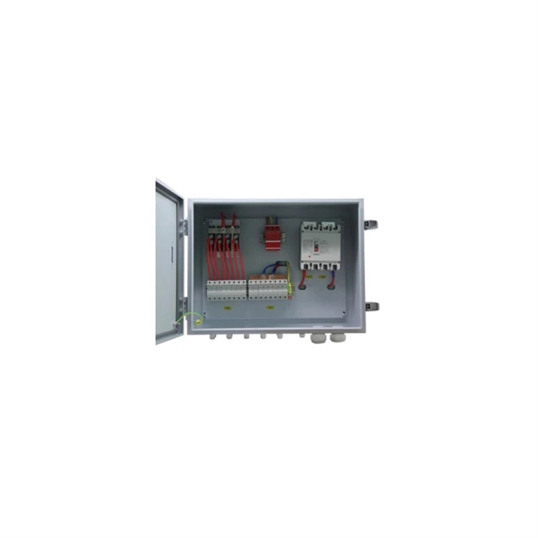
The formula for calculating electrical box size is: . The formula for calculating electrical box size is: . Free electrical load calculation tool for residential and commercial buildings. Calculate service entrance sizing, panel loads, demand factors, and ensure NEC Article 220 compliance. Important: Load calculations must comply with NEC Article 220 and local codes. Always verify calculations with a. How to choose a distribution box of the right size for a project based on load current? If you're like most electrical professionals, picking the right distribution box for your project can feel like navigating a maze. I've been in those shoes - staring at spec sheets, worrying about. The National Electrical Code (NEC) specifies minimum box sizes based on wire gauge and quantity. Proper sizing ensures safety, ease of maintenance, and compliance with regulations. This calculator helps you determine the minimum required box volume based on the number of wires, devices, ground wires, and clamps involved. This ensures compliance with electrical codes and prevents overcrowding. Choose a standard or custom box volume watch capacity update with clear pass or fail status plus tips examples CSV and PDF export for documentation Works for common sizes supports.
[PDF]
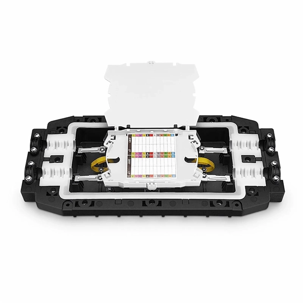
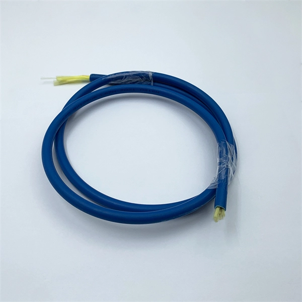
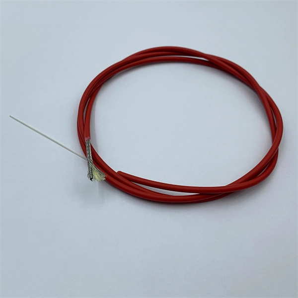
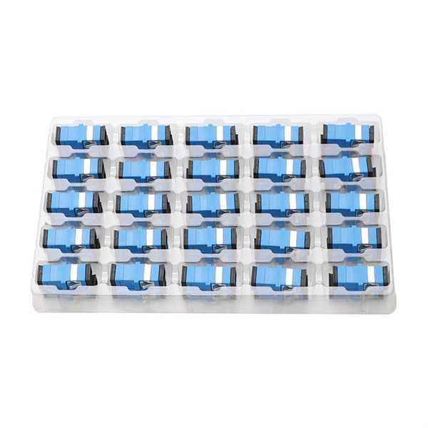
Calculate split loss, excess loss, and terminations for any ratio quickly today. See power budget impact instantly, then download a CSV or PDF summary. Use 2×N when two inputs feed the same distribution stage. Common values: 2, 4, 8, 16, 32, 64. Wavelength is recorded in. Fiber optic joints or terminations are made two ways: 1) splices which create a permanent joint between the two fibers or 2) connectors that mate two fibers to create a temporary joint and/or connect the fiber to a piece of network gear. Either joining method must have three primary characteristics. Optical fiber channel insertion loss is the decrease in optical power that occurs when an active transmitter is linked to an active receiver via terminated, optical fiber cables and patch cords and may include splice points and optical couplers. In general, loss is the natural decay of a signal. Telcordia and TIA allow a 0. 3 dB maximum splice loss. Connector loss is always measured as a mated pair. ITU & IEC allow 0. Splitter loss values are "Typical" and include a connector in and out. These terminations must be of the right style, installed in a. In this lesson, a long and very important one, you will learn about fiber splicing and termination. Wavelength is recorded in outputs for documentation.
[PDF]
BroadbandUSA collected information about network construction expenses to increase awareness of the costs associated with deploying a broadband network. This information can help project leaders engag.
[PDF]
Free electrical calculators for wire sizing, voltage drop, load calculations, conduit fill & power factor. NEC compliant tools for electricians & engineers. In this guide, we'll break down everything you need to know to install a distribution box correctly and confidently. Choose the right box based on environment (indoor/outdoor), load capacity, and durability. Check for proper IP/NEMA ratings and material quality. Ensure safe placement: install in. Professional electrical wire sizing tool based on National Electrical Code (NEC) standards. Calculate proper wire gauge, voltage drop, and ampacity for safe electrical installations. Input your electrical parameters to get accurate wire size. Pro Insight: A well-planned distribution box feels like a silent partner—you only notice it when something's wrong. Our goal? Make sure you never notice it. Before we dive into calculations, let's get familiar with a few essentials: 1. Create accurate bids and win more projects with automated formulas. The sizing requirements for pull boxes, junction boxes, handhole enclosures, and conduit bodies exist to prevent conductor insulation damage. Those requirements are in 314. 28, and they apply to all conductors 4 AWG and larger (Fig. To illustrate how these requirements prevent conductor. Estimate wire ampacity with derating factors for temperature and conduit fill. Reference tool based on NEC guidelines. It is NOT a substitute for professional.
[PDF]
This article will focus on the failure rates of optical modules, analyze the primary causes of failure in traditional Digital Signal Processing (DSP) modules, compare failure rates utilizing LPO technology, and discuss the advantages presented by LPO modules. Linear Pluggable Optics (LPO) are a new optical transceiver technology. The idea is simple: instead of a DSP (digital signal processor) inside the module – replacing it with transimpedance amplifier (TIA) and a driver chip with high linearity and EQ capability – LPO shifts signal processing into. Copyright 2023, Coherent. Next-generation 400G and 800G modules for data centers, AI clusters, and telecoms — validated in a European lab, ready to ship from Europe. What is Low-Power Optical Transceivers (LPO)? Linear Pluggable Optics (LPO) replace the DSP inside the optical module with linear analog components, shifting. QSFP-DD LPO TRANSCEIVER DESIGNED FOR PCIE® GEN 5. 0 over optical link, enabling scalable server disaggregation and efficient rack-to-rack interconnects ideal for AI/ML and. Led by Cisco Optics experts, this MSA quickly gained broad industry support due to its vision to create cost-effective solutions for high-density multi-terabit switching, routing, and transport networks. The goal was to define optical specifications that allow for future 100G and 400G pluggable.
[PDF]

Towers are not rooted by only pouring concrete—they require extensive soil analysis, wind loads, types of towers, and seismic activity to determine the necessary foundation for safety and sustainable use. A communication tower foundation design is the structural blueprint that determines the anchor point of the tower on the ground. This article delves into the intricate process of civil construction tailored. Tower owners must comply with a multi-layered regulatory, engineering, and safety framework that governs tower siting, where a cell tower can be built, how it must be designed, and how it operates throughout its lifecycle. These requirements ensure public safety, structural integrity, regulatory. Here are six foundation types for communication towers that work for a wide range of situations and environments. If you're planning a new installation, knowing the basics of these foundations can help you establish a secure and durable tower that will be a community asset for years to come. Telecom (Telecommunications) towers are a generic description of radio masts and towers built primarily to hold telecommunications antennas. As such antennas often have a large area and must be precisely pointed out, such towers have to be designed and built to limit wind induced movement. The Contractor shall employ a quality control program that will ensure that engineering, fabrication.
[PDF]
This involves achieving thermal resistance values of less than 1°C/W for high-power optical components and ensuring temperature uniformity across the package to prevent thermal gradients that could degrade system performance. Being an industry group uniting representatives of the data and optical worlds, OIF's purpose is to accelerate the deployment of interoperable, cost-effective and robust optical internetworks and their associated technologies. Optical internetworks are data networks composed of routers and data. Co-packaged optics (CPO) has emerged as an ultimate solution for achieving the ultra-high bandwidths, shoreline densities, and energy efficiencies required by future GPUs and network switches for AI. Microring modulators (MRMs) are well-suited for transmitters due to their compact size, high energy. Source: IEEE 802. 3 Beyond 400G Study Group. CPO is widely regarded as a promising. The rapid surge in global data traffic, driven by artificial intelligence and hyperscale data centers, has established copackaged optics (CPO) as a pivotal technology for next-generation high-bandwidth and low-power interconnects. Introduction The CPO JDF plans to release three documents focused on different elements of Co-Packaged Optics (CPO): the.
[PDF]
This is the latest revision of this Recommendation that was first created in 1988. Recommendation ITU-T G. 654 describes the geometrical, mechanical and transmission attributes of a single-mode optical fibre and cable which has the zero-dispersion wavelength around 1300 nm wavelength, and which is loss-minimized and cut-off wavelength shifted at around the 1550 nm wavelength. The superior attributes of TXF ® optical fiber, compliant to ITU-T G. E, allow for the provision of an additional network margin that can be leveraged to enable reliable, high-data-rate transmissions over longer spans and extended reach. This allows long-haul networks with TXF fiber to be. ACOME and Sumitomo Electric have developed a new hybrid solution that allows network operators to deploy a single universal cable that supports both current and future network needs. Upgrading to 800G and above requires fewer repeaters to amplify the optical signals and can also avoid the need for. Recommendation ITU-T G.
[PDF]