
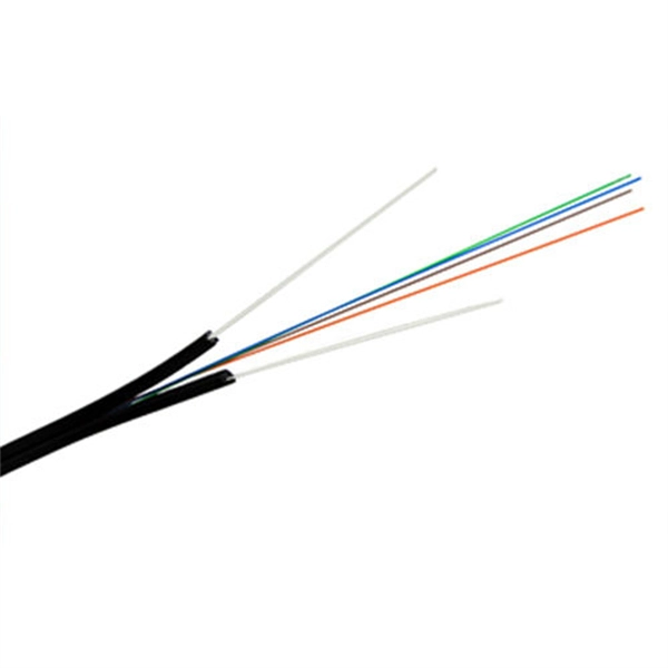
A8: Yes, multimode fiber optic cable can support high-speed data transmission depending on the fiber type and network equipment used. Multimode fiber (MMF) is an optical fiber designed to carry multiple light propagation paths—or modes—simultaneously. This is made possible by its relatively large core diameter, typically 50 or 62. 5 microns, compared to the ~9-micron core in single-mode fiber. The wider core accepts light from. Multi-mode optical fiber is a type of optical fiber mostly used for communication over short distances, such as within a building or on a campus. Multi-mode links can be used for data rates up to 800 Gbit/s. Multi-mode fiber has a fairly large core diameter that enables multiple light modes to be. In the realm of telecommunications and networking, multimode fiber optic cable plays a crucial role in efficiently transmitting data over short to medium distances. This guide aims to provide a concise understanding of multimode fiber optic cable and its applications. These fiber cables are structurally designed to transmit several light signals simultaneously, each of which is directed. Unlike copper cables, which rely on electrical signals, fiber optics use pulses of light to transmit data—offering unmatched bandwidth, low interference, and long-distance capabilities. But not all fiber cables are created equal: multimode (MM) and single mode (SM) fibers are the two primary types.
[PDF]
Use this distributed feedback lasers buying guide to compare major types, define selection criteria, and find suppliers: Professional purchasing of high-value photonics products is a substantial responsibility, where a structured decision-making process is essential. RP Photonics offers a lot of. Clicking the "Choose Item" drop-down opens a list containing all of the in-stock lasers around the desired center wavelength. LIV and spectral measurements can be downloaded by clicking the red icon corresponding to each serial number. The DFB1550P laser diode is available as a turnkey laser system. DFB or distributed feedback laser diodes are single-frequency laser diodes that usually operate from 783 to 1625 nm (higher wavelength also available). The output wavelength of the DFB laser depends upon the effective refractive index and period of the grating. Covering NIR to LWIR wavelengths (750nm–17µm), these lasers feature integrated DFB gratings and TEC cooling for robust. Distributed Feedback (DFB) and Distributed Bragg Reflector (DBR) laser diodes feature a frequency-selective structure within the laser chip, which restricts the laser emission to a single longitudinal mode. GLSUN designs and manufactures 2. 5Gbps, 10Gbps, and 25Gbps distributed feedback (DFB) laser diode chips for fiber optic transceivers, PON, access, optical Ethernet, SDH, 5G, and data center applications. 5G DFB laser diode chips are available in wavelengths 1270nm, 1310nm 1490nm.
[PDF]
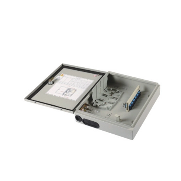
They are the bridge between fiber optic cables in the field and the equipment or patch panels that manage them. By combining factory-installed connectors with spliced bare fiber, pigtails ensure that network installers can create fast, reliable, and cost-effective terminations. Fiber pigtails are simple in appearance, yet essential in function. Get the wrong connector type, the wrong polish, or skip proper fusion splicing technique—and you're looking at elevated signal loss, increased back reflection, and a. In such contemporary fiber optic communication systems, low-loss, and connectivities, which have reliability, are crucial for not only maintaining high-speed but also high-quality data transmission. The most urgent stage of the process is, in fact, separating fiber optic pigtail, also known as. High performance optical pigtails are a defining factor in ensuring any network performs to the highest level. Prysmian ofers an extensive range of optical pigtails for use in FTTx, telecommunications, data communications and CATV applications. All pigtails are fully qualified to Telcordia GR326. A fiber optic pigtail is a type of fiber optic cable with only one end that has a factory-terminated connector and the other end exposed as bare fiber. Characterized by having an optical fiber connector on one end and a bare fiber end on the other, they are primarily used to connect optical transceivers or other optical.
[PDF]

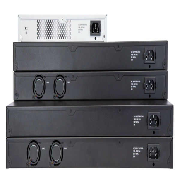
Optical modules convert electrical signals into light to move data quickly and reliably in AI systems, enabling fast and smooth data processing. Using advanced optical modules boosts AI system speed and bandwidth, helping handle large data loads with low delay and high efficiency. Optical modules. Laboratory utilities: framework for communication with laboratory equipment and post-processing of data (opticomlib. You can install opticomlib using pip: or from source code: NumPy Compatibility: binary_sequence and electrical_signal now fully support NumPy protocols, allowing direct use with. The optical module serves as a crucial component in optical fiber communication systems, operating at the physical layer, which is the lowest layer in the OSI model. Its primary function is to achieve optoelectronic conversion by converting electrical signals into optical signals and vice versa. An. Learn about the components inside a coherent optical engine, what they do, and how they use modulation to send and receive data. Optical communications over metro, long-haul, and submarine networks once used simple direct-detect technology. That's no longer the case.
[PDF]
Facility location affects data center interconnection more than you might expect. High-performance interconnects and access to quality networks are two of the most vital considerations when selecting a colocation provider. However, without a strategic location, these benefits. Data center interconnect (DCI) is private network connectivity between multiple data center facilities that lets you treat geographically separated infrastructure as a unified environment. Instead of routing traffic between sites over the public internet, DCI uses dedicated circuits that provide. Interconnection is an over-arching term that refers to many different physical and virtual connections companies can select to exchange data, provide business continuity and customer services, and address specific business objectives. Interconnection in colocation data centers are vital for fast. Following are some of the drawbacks or limitations of data centers. Limited Local Control: Companies outsourcing to data centers have less direct control over their infrastructure because the hardware and support staff are located remotely. Data center facilities can work together by sharing resources and passing workloads between one another. This interconnection is typically achieved through high-capacity interfaces, including dedicated private lines, dark fiber, Ethernet, and internet-based connections. With DCI, SPs can host critical.
[PDF]
This article discusses such episodes, known as data center outages, looks at their causes, and shares best practices for preventing them. Malfunctioning Hardware 3. Environmental and Natural Disasters 6. Software Failure. 2025 revealed how data center outages, from fires and mechanical failures to hyperscale cloud region events, can cascade quickly in an AI-driven world, highlighting the growing importance of physical resilience, control-plane reliability, and clean recovery. Physical infrastructure failures, such. As hyperscale AI campuses expand and real-world attacks strike supporting systems, the gap between how data centers operate and how they're protected is becoming harder to ignore. AWS Outage: What Are the Lessons for Enterprises?. Fault-tolerant systems are systems that are engineered to detect failures, isolate faulty components, and recover quickly without significant impact on operations. This is achieved through a combination of physical, logical, and data redundancy, sophisticated fault detection mechanisms, and. Data center failures can be caused by a variety of factors, some of which are common and impact most people (such as human error), while others are rare. Whether it is rare or not, the impact is usually the same: lost productivity, poor service that affects customers or staff, and costs more. Introduction to Fault Detection through BMS 2. Fault Detection & Diagnostics (FDD): Component Breakdown 5. Predictive &.
[PDF]

The primary and backup data centers, planned for the Absheron and Hajigabul regions, will incorporate advanced technologies to minimize carbon emissions. These facilities will feature energy efficiency, water conservation, waste recycling, and natural cooling systems to preserve. We currently have 3 data centers listed, from 1 markets in Azerbaijan (Az?rbaycan). Click on a market below, to explore its data center locations. Save the trouble of contacting the providers yourself, check out our Quote Service. The European Investment Bank will provide €43 million ($44. First reported by Azernews, the funding will be used to develop two data centers for AzInTelecom LLC which will be located Absheron and Hajigabul regions. AzInTelecom. Two innovative data centers utilizing green technologies and decarbonized materials will be constructed in Azerbaijan, operated by "AzInTelecom" LLC under the Ministry of Digital Development and Transport. Work is underway in Azerbaijan to launch two new data centers as part of ensuring the transition of all government institutions to the Government Cloud and in order to expand cloud services,.
[PDF]

In this guide, we take a deep dive into the design, performance, and applications of liquid cold plates, which are essential for thermal management in industries like data centers, telecommunications, aerospace, and defense. In this study, we conducted an experimental study on the heat sink performance at a constant volumetric airflow rate under various pressure conditions and verified the effect of the change in the density of the working gas on electronics cooling performance. First, we measured the flow rate of. Electronic circuits and systems designed for earth orbiting space applications and outer planetary exploration are required to operate reliably and efficiently under extreme temperature conditions. This requirement is dictated by the fact that the operational environments associated with some of. Cold plate cooling systems are revolutionizing how high-performance electronics manage heat in demanding environments. EMS providers deliver production-ready electronic systems for applications such as avionics, radar, communications, and unmanned platforms, with processes. For aerospace and space applications, where packaging and the optimal use of space, weight, and power are important, adequate and efficient cooling is a limiting factor due to the increased heat flux rates from compact-design electronic units. From a thermal energy management perspec-tive, immersion cooling is better than.
[PDF]

Solar energy offers data centers a path to reduce their carbon footprint and operational expenses. Major tech companies like Google and Apple are already leading the way, demonstrating that solar-powered data centers are environmentally responsible and economically viable. Data centers are the backbone of our digital world, powering everything from streaming services and cloud storage to remote work platforms and IoT devices. As our reliance on digital infrastructure grows, so does the energy consumption of these mission-critical facilities. Currently, data centers. Solar offers clean power at predictable costs, can be built fast at many scales, and pairs well with batteries to deliver reliability. In this article, we explain why data centers use so much energy, how solar powers data centers, how batteries and microgrids keep servers online, and why these. 2022 to 35 gigawatts (GW) in 2030. The United States accounts f d tap into suitable energy sources. Renewable energy is the answer, but it must be cost-efective, able to meet enormous demand without inte zed by explosive growth and demand. The emergence of AI, data streaming, cloud computing, and.
[PDF]
Bogdan Sirbu: One example I can think of is the H2020 L3MATRIXproject. On this project, we developed a 2D matrix of 64 different transceiver and receiver cells, achieving high radix and getting an extend.
[PDF]

We will look at how to interpret PLC LED status indicators for digital inputs and outputs and how to perform troubleshooting tests using a Digital Multimeter. This section includes the block diagram of the DI 16x24VDC ST module with the terminal assignments for a 1-wire connection. Information on wiring the BaseUnit can be found in the system manual ET 200SP distributed I/O system. The load group of the module must begin with a light-colored BaseUnit. How to wire real-world signals into the Logo's digital inputs to detect whether a machine is running. Covers stack lights, door sensors, relay contacts, and proximity switches — with a complete wire diagram and step-by-step instructions for both electrical engineers and IT teams. You have a Siemens. PLC and DCS control systems Wiring Diagrams for Digital Input (DI), Digital Output (DO), Analog Input (AI), and Analog Output (AO) signals. be responsible or liable for indirect or consequential damages resulting from the use or application of this equipment. The examples and diagrams in this manual are included solely for illustrative purposes. Because of the many variables and requirements. This manual contains information that is necessary to use the NX-series Digital I/O Unit. PLC programs rarely cause failures, so in this article, we'll assume that there are no program errors and that the fault originates in the.
[PDF]
The development of the relay protection based on open architecture is a relevant direction of electrical and electronic engineering. The paper presents the problem of the modern microprocessor-based relay prote.
[PDF]

An Optical Splitter, also known as a beam splitter, is a passive optical device that divides a single input optical signal into two or more output signals. Conversely, it can also combine multiple signals into one. Knowing the difference between a splitter and an optical coupler helps you build better networks. You make your network work better when you pick the right device for each job. You can connect many users to one port with 1:n or 2:n splitters. By dividing a single optical signal from a central Optical Line Terminal (OLT) into multiple outputs for Optical Network Terminals (ONTs) at users' homes, splitters eliminate the need for dedicated fibers to each residence—slashing infrastructure costs while scaling network reach. This guide. In a Passive Optical Network (PON), a single optical fiber carries massive amounts of data using light. Signal Input: The fiber splitter receives the optical signal from the upstream network node and enters the splitter through the input fiber. Signal Distribution: Inside the splitter, according to the design structure and different. Splitters are passive optical devices that divide or combine optical signals, and they come in various types, including power splitters, uneven splitters, and wavelength-division multiplexing (WDM) splitters. Each type serves specific applications, enabling efficient use of optical infrastructure.
[PDF]

A ladder type cable tray tee is a fitting used to create a branch in a cable tray system, allowing cables to be routed in three directions. Its "T" shape provides a secure and efficient way to split cables from a main tray into two separate paths, ensuring organized and flexible. A cable tray tee and tee cover are components used in cable management systems to support and protect electrical and data cables. Here's a brief explanation of each:. Rigid steel cable tray tee fitting with zero tangent, safety bottom, and full accessory support. ventilation to heat producing cable such as power communication and other with the same or different width of the cable run. All fittings are available in sizes and types corresponding to the straight cable tray sections. These fitting are including: elbow, horizontal cross, vertical inside. NOTE : Equal or un equal tees can be supplied. When ordering state widths W1xW2xW3.. Office: 147/22 Nguyen Sy Sach Street, 15 Ward, Tân Binh Dist, HCMC,VN. Is it possible to connect 2 cabletrays with a "branch piece (left picture)" instead of a "tee (right picture)". The tee has 3 connectors, the branch piece only has 1 connector. I would like to ajust the "Type properties -> Fittings -> Tee" with the branch family, but can't get it accomplished.
[PDF]

Cable Trays* — Max two 24 in. (610 mm) wide by max 6 in. (151 mm) deep open-ladder cable tray with channel-shaped side rails formed of 0. 54 mm) thick aluminum or min 0. In practice, cable tray dimensions are a system of interrelated measurements —width, depth, length, and material thickness—that directly affect cable fill compliance, heat dissipation, structural loading, and long-term expandability. From an engineering standpoint, cable tray dimensions are not. Perforated Cable Tray System expertly constructed from high-grade stainless steel, offering exceptional durability and resistance to corrosion. With side height 100mm. A properly designed and installed cable tray system will provide. Studs — Wall framing to consist of wood studs or channel shaped steel studs. Wood studs to consist of nom 2 by 4 in. Additional studs shall be used to completely frame. Best Size: Here, deep trays (75mm to 150mm) are used since power cables are typically thick and heavy. Data cables, such as your Wi-Fi or computer ones, are extremely sensitive. They do not get hot; however, they do not like to hang or sag. In case a data cable folds in an excessive manner, the. ect the minimum bend ra-dius for cables as they exit the bottom of the cable tray. A rung spacing of 6 to 9 inches (150 to 230 mm) is preferable when the cable tray cont d for instrumentation and control applications that require additional protec eferred to support and protect numerous small.
[PDF]

