The communication system of fiber optics is well understood by studying the parts and sections of it. The major elements of an optical fiber communication system are shown in the following figure. The ba.
[PDF]
Our ultra-low polarization dependent loss couplers offer low levels of sensitivity to polarization, enable more effective monitoring and management of optical networks. These couplers are available in a wide range of split ratios, lengths, and packaging. Custom terminations are also. Pasternack directional couplers are passive devices that couple part of the transmission power in a transmission line. Our directional couplers provide the bandwidth, high directivity and higher power that engineers need for their most demanding application designs. RF directional couplers often. Corning's optical couplers are fused fiber branching devices that split off a portion of light to allow for optical monitoring and feedback. These devices are used extensively in fiber amplifier power control, and in transmission equipment for performance monitoring and feedback control. Our. Narda-MITEQ manufactures and designs a line of RF and Microwave coaxial Directional Couplers, covering a wide range of applications from DC to 40 GHz. These Directional Couplers boast both superior performance and reliability. These couplers provide simple solutions for many applications including electronic warfare (EW). Our Xinger ®- brand directional couplers offer you the lowest loss in the industry for their category. The term “coupling” comes from multiple eigenmodes of a waveguide interacting with light, resulting in light being transferred between the modes. Small parts of.
[PDF]
This report studies the global Optical Communication Module production, demand, key manufacturers, and key regions. The global Optical Module For Communication market size was US$ million in 2024 and is forecast to a readjusted size of US$ million by 2031 with a CAGR of %during the forecast period 2025-2031. 7% during the forecast period MARKET INSIGHTS The global Active Optical Module Market was valued at 5916 million in 2024 and is projected to reach US$ 15140 million. Major optical modules manufacturers and suppliers: Innolight, Eoptolink, Huagong Tech, Linktel, Accelink, CIG ShangHai CO. Upstream optical devices manufacturers and suppliers: TFC, T&S Communications, Advanced Fiber Resources, Borui Technology, Optowide Technologies. Upstream optical chips. Global Optical Modules Market Size By Product Type (Transceivers, Transponders), By Technology Type (Single-Mode Fiber (SMF), Multi-Mode Fiber (MMF)), By Application (Telecommunications, Data Centers), By Data Rate (10 Gbps, 25 Gbps), By Form Factor (SFP (Small Form-Factor Pluggable), SFP+. Additionally, strategic partnerships and acquisitions are prevalent, enabling companies to access new technologies, markets, and expertise. Market Share Analysis: Product Portfolio: Offering a comprehensive range of solutions across different segments, from access networks to long-haul.
[PDF]

This guide provides a complete framework for understanding, identifying, and planning MPO connector gender in data center environments. Visually, male and female MPO connectors are easy to distinguish: male connectors feature two alignment pins (PIN pins), while female connectors have corresponding holes instead of pins. An MPO connection is made between a male and female connector to make sure that there is proper alignment. Interfaces on active MPO equipment, such as transceivers are usually male, so any MPO trunk cable. In modern data centers and high-density fiber optic networks, MPO (Multi-Fiber Push-On) connectors have become an essential solution for achieving fast, reliable, and scalable connectivity. You will discover the physical distinctions between male and female connectors and how to develop a gender strategy for your infrastructure, which gender connects. Whether you're supporting parallel optics like 100G SR4 or densifying an optical distribution frame (ODF), MPO is now a cornerstone of network design. This article explains: And a practical checklist to design MPO systems that scale cleanly. If you only remember one thing: MPO is a multi-fiber. In MPO and MTP fiber connector systems, Male vs Female and Pin vs No-Pin describe the same core engineering attribute: the presence or absence of alignment pins on the MT ferrule. Unlike single-fiber connectors such as LC or SC, this distinction is not optional terminology but a mandatory.
[PDF]

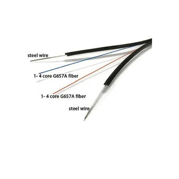
Fiber optic cables offer superior performance compared to copper cables, especially over long distances. They provide higher data transmission rates, larger bandwidths and are immune to electromagnetic interference. Fiber optic cables and copper wires are the two primary types of cables used in networks. Fiber optic cables transmit data using light waves, enabling higher. Fiber optic tends to be the more premium solution, while copper wiring is far more common, but why is that? What are the differences between these two cable types, and why might you want to pick one over the other? Here's everything you need to know about fiber vs. Copper wire is more susceptible to interference and has limited data capacity, making optical fiber the preferred choice for modern high-speed. If you're deciding between copper and fiber optic cables, it's not just a question of cost, it's about purpose, environment, and future readiness. Both have distinct strengths that can serve very different networking needs depending on your setup. Fiber optic cables provide. In today's fast-paced digital world, choosing the right network cable can significantly impact the performance, reliability, and security of your communications infrastructure. Among the most commonly used cables are copper and fiber optic cables, each offering unique advantages depending on the.
[PDF]
G652D optical fiber has been in use for almost 30 years in optical communication. There are two types of optical fibers: single-mode and multi-mode. These modes in optical fibers refer to the pattern of light traveling inside them. G652D is a. G652D optical fiber has been in use for almost 30 years in optical communication. There are two types of optical fibers: single-mode and multi-mode. These modes in optical fibers refer to the pattern of light traveling inside them. G652D is asingle-mode optical fiber; only one light pattern can travel inside it. It has been a favourite because of i. Advantages of the fiber optic cable are as follows: 1. Polarisation Modal Dispersion (PMD) is when two polarisations of light travel at different speeds, causing the spreading of the signal. This spreading reduces the signal strength. The G652D fiber offers a higher PMD performance compared to G652C. 2. Water peaks are where the water molecules are. Theadvantages of optical fibertechnology have offered many applications for G652D fibers. ITU-T G652D single-mode fibers are primarily used in networking and communication. You can use the G652D fibers for both short- and long-range networking applications. For example, you can use these fibers for LAN, MAN, and access networks. TheseG652D fibers h.
[PDF]

This comprehensive guide will explore the importance and benefits of this integration, provide an understanding of fiber optic cable and Ethernet ports, discuss their compatibility, and offer a step-by-step process for connecting them. Proper connection of fiber optic cables is essential to harness these benefits fully, as even minor errors can lead to significant performance issues like signal loss. This article will guide you through the necessary tools, materials, and methods on how to connect fiber optic cables effectively. Using an optical cable involves connecting it to the right equipment, ensuring proper installation, and testing the system for optimal performance. Here's a step-by-step guide on how to use optical cable effectively: 1. Check Compatibility of Equipment Ensure that your equipment (e., network. One powerful solution to achieve these goals is by connecting fiber optic cables with Ethernet ports. This comprehensive guide combines industry standards with field-tested practices to ensure you achieve a rock-solid. These transceiver modules are hot-swappable input/output (I/O) devices that plug into 100BASE, 1000BASE and 10GBASE ports (for SFP+), which connect the module port with the fiber-optic or copper network. The SFP transceiver modules are hot-pluggable I/O devices that plug into module sockets. The number one cause of signal loss in optical fiber installations is dirt on.
[PDF]
The optical communications industry contributes $3. 7 trillion to global GDP annually, accounting for 3. The telecom sector, which relies heavily on optical communication, supports 12 million direct and indirect jobs worldwide. At the same time, the technology leap from 5 ms copper like latency targets to sub 1 ms data. The global optical communication systems and networking market size was valued at USD 36. 87 billion in 2025 and is projected to grow from USD 38. 38% during the forecast period. 3%, according to the latest report published by Global Market Insights Inc. 62 USD Billion in 2024. 22 USD Billion by 2035, exhibiting a compound annual growth rate (CAGR) of 7. As AI clusters expand and high-performance computing requirements increase, key technologies such as 800G and 1. 6T optical transceivers, silicon photonics, and. Optical networking is a form of communication that employs light-based signals to send data via a variety of telecommunications networks. This report focuses on the different segments of the Optical Communication and Networking market (Component, Technology, Application, Data Rate, Vertical, and.
[PDF]

Some of the most common optical passive components include optical couplers, optical splitters, optical filters, optical connectors, optical attenuators, optical circulators, optical isolators, optical switches, and optical add/drop multiplexers. Optics engineering focuses on transmitting data using light, a method providing the high speeds and vast bandwidth necessary for modern digital life. Passive optical components play a fundamental role within this infrastructure. These engineered devices manage and direct light signals through a. A passive optical network is a point-to-multipoint network architecture to serve multiple premises. It allows communication service providers to serve several customers using a single connection. There is no need for any active components for electrical-to-optical or optical-to-electrical. Passive optical components play a pivotal role in high-speed, long-distance communication networks, such as fiber optic networks, to ensure efficient and secure data transmission over vast distances without the need for external power supplies.
[PDF]

The maximum distance of copper is around 328 feet (100 meters), which is a far shorter range than is offered by either of the fiber optic cable types. This is because fiber optic cable is not affected by attenuation, dispersion, or EMI in the same way that copper is. Many factors decide the fiber cable distance, but the key factors include the below six aspects. Attenuation First is the attenuation of the optical fiber. For some. Fiber optic cable transmission distance is determined by two primary physical factors that affect signal quality as light travels through the fiber medium. The selection of fiber optic cables over copper wires or vice versa depends on factors such as bandwidth, distance, and cost of transmission. Fiber optic cables transmit data using light waves, enabling higher. Fiber optic cables have revolutionized modern communication networks by enabling blazing-fast data transmission across vast distances. However, fiber cable runs are not limitless. However, fiber optic cable performance. Q: Is there and electromagnetic interference with optic cables? A: The fiber is glass and the cable is plastic, neither of which are affected by electromagnetic interference. There is a cable used in electrical transmission lines called OPGW- optical power ground wire - that has fiber inside a wire.
[PDF]
Optical modules, also known as optical transceivers, are essential components that convert electrical signals to optical signals and vice versa. They form the backbone of long-distance, high-capacity data transport in modern telecom networks. That is, metal medium communication represented by coaxial cables and network cables is gradually being replaced by optical fiber media. These modules typically consist of a transmitter, which converts electrical signals into a light signal, and a receiver, which converts the received signal back. Optical communication, also known as optical telecommunication, is communication at a distance using light to carry information. It can be performed visually or by using electronic devices. If you're dealing with data centers, telecommunications, or AI networking, grasping the key parameters of an optical. Stay up-to-date with the latest optical communications trends. We design and manufacture a broad range of high-performance fiber optic components and integrated modules for original equipment manufacturers (OEMs) within the optical network equipment market. Corning's end-to-end fiber solutions form. Therefore, NASA is developing optical communications to address limitations of radio frequency (RF) communications, including: bandwidth, spectrum and overall size of frequency packages and power used. Optical spectrum uses light as a means of transmitting information via lasers.
[PDF]
The main trade show for the large optical module industry is the Optical Fiber Conference (OFC), that is held annually in southern California. Other prominent shows for the industry include ECOC in Europe and FOE in Japan.
[PDF]
Connectorized attenuators often have a quite compact housing, essentially looking like a fiber-optic adapter. Some of these devices provide a fixed level of attenuation, quantified as the insertion loss in decibels. An optical attenuator, or fiber optic attenuator, is a device used to reduce the power level of an optical signal, either in free space or in an optical fiber. The basic types of optical attenuators are fixed, step-wise variable, and continuously variable. Optical attenuators are commonly used in. Fiber-optic attenuators are a specific type of optical attenuators which are used in fiber optics, e. for achieving a suitable signal level for a data receiver in a telecom system. It primarily ensures the power or amplitude of a signal is lowered without significantly distorting its waveform. The attenuator circuit will allow a known source of power to be reduced by a predetermined factor, which is usually expressed as decibels.
[PDF]

Select the correct wavelength and set your reference. You measure optical power in dBm or insertion loss in dB. Consistent procedures ensure accuracy. Measure total signal loss from fiber, connectors, or splices. Optical fiber attenuation is the attenuation per unit length of optical fiber, and the unit is dB/km. When connecting two optical fibers, there will be loss inside any connector or joint. Consistent measurement techniques. While optical power meters are the primary power measurement instrument, optical loss test sets (OLTSs) and optical time domain reflectometers (OTDRs) also measure power in testing loss. TIA standard test FOTP-95 covers the measurement of optical power. Optical power is based on the heating power. Light Source: The CMA5 Series Light Sources provide an economical and stable laser source for use in point-to-point attenuation measurement. They feature a rugged design, built to withstand the difficult testing environment of fiber optic cable installation and maintenance. The CMA5 Light Sources. When talking about optical measurements, wavelength basically means how far a wave pattern repeats itself, usually measured in nanometers (nm). Commonly, a power meter on its own is used to measure absolute.
[PDF]

To use a power meter for fiber optic testing, always clean connectors first with lint-free wipes or click-to-clean tools. Select the correct wavelength and set your reference. You measure optical power in dBm or insertion loss in dB. Consistent procedures ensure accuracy. Verify light travels from. The most basic fiber optic measurement is optical power from the end of a fiber. This measurement is the basis for loss measurements as well as the power from a source or presented at a receiver. Typically both transmitters and receivers have receptacles for fiber optic connectors, so measuring the. An optical power meter measures the strength of light traveling through a fiber optic cable, giving you a reading in dBm (decibels relative to one milliwatt). This article will guide you through the methods, instruments, and key considerations for measuring fiber. Fiber optic cabling is the high-performance core of today's datacom networks. As network speeds and bandwidth demands increase, fiber performance requirements have become more stringent. Fiber testing is more important than ever. An OPM uses a photodiode to generate an electrical current proportional to optical power.
[PDF]


