Switches come in three types: those with purely Ethernet ports, those with purely optical ports, and those with a combination of both. Port types are limited to two: optical and Ethernet. Optical ports on switches typically accommodate optical modules for. The optical ports on the switch are usually paired together, with one TX sender and one RX receiver. The. Optical switching represents a fundamental technological evolution, shifting data routing from the domain of electrons to the realm of photons, or light. This transition allows data to remain in its native optical form as it travels through fiber optic networks, eliminating the need for. An all-optical Ethernet switch is a network switch whose service ports are entirely optical, meaning every interface uses fiber rather than copper. This design enables end-to-end optical signal transmission, avoiding the conversion between electrical and optical signals at the switch port level. Copper ports, also known as RJ45 ports, are the most common type of Ethernet switch ports. These ports use twisted-pair copper cables (Cat5e, Cat6, Cat6a, etc. Copper ports are widely used in local area networks (LANs) due to their cost-effectiveness and ease of installation. They can function as core, aggregation, and access devices on campus networks and connect to upstream and downstream devices.
[PDF]

Use two fibers: one dedicated to TX, the other to RX. Both sides transmit and receive at the same wavelength (common values: 850 nm MM, 1310 nm/1550 nm SM). The front panel is usually labeled TX and RX, and you cross-connect TX→RX, RX→TX with a duplex patch cord. Switch optical port intercommunication means that the optical fiber ports of two switches are connected to each other to achieve the purpose of network connection. The connection between two or more Ethernet switches in a certain way (Uplink port, etc. ) is called the cascade. SFP modules insert into these slots and and require two strands of fiber, typically duplex Using multi mode fiber (for runs under 1000 feet) or duplex single mode fiber (for runs over 1000 feet). This is a cost-effective and high performance way to connect network switches. Use one fiber strand for both. The switch supports 10 Mbps, 100 Mbps, and 1000 Mbps connections. Using Gigabit Ethernet (1000 Mbps), the switch sends files across the network at speeds up of to 2000 Mbps due to the full-duplex nature of Gigabit Ethernet connections. You can either connect 24 Ethernet copper cables or 22 copper. Port types are limited to two: optical and Ethernet. Optical ports on switches typically accommodate optical modules for transmitting data via fiber optic cables. In situations where there's a shortage of Ethernet ports, some users may insert Ethernet port modules into optical ports to connect with.
[PDF]
Step 3 Remove the cables or optical modules from the old card. Press the two green locking clips in the middle of the card to eject the ejector levers. Turn the ejector levers outward and slowly pull the card out. Place the replaced. Unplug the optical fibers from the optical module before removing it. Install or remove optical fibers carefully to avoid damaging the fiber connectors. If an optical module cannot be completely inserted into an optical. Page 7 Optical port USB storage device Wi-Fi terminal 1. Wear an ESD wrist strap or ESD gloves when replacing the optical module. Therefore, replace an optical module only when you confirm.
[PDF]

There are 48 bicolor LEDs (green/amber) for the first 48 SFP+ ports and 16 tricolor LEDs (green/amber/white) for the SFP-DD ports. The last set of LEDs pulse once in white before indicating the FC port status in green or amber. When it blinks white twice, it shows the status of the second port of the SFP-DD. The port status LEDs for the FC ports are arranged left and right to correspond to the upper and lower ports respectively in each pair. LEDs on the port side of the switch Table 1. LEDs on Cisco Catalyst 9500 Series Switches 1 Available only on switches with 10G ports. System LED Indicator System is not operational. System is operating normally. As a group or individually, the LEDs show information about the switch and about the ports Preventing Overload - Each port that provides PoE has a maximum power it can deliver. Three LEDs are used on each port. Ports on the Cisco Catalyst switch do not have LEDs. Not the question you're searching for? Each. Number of LEDs per port - Ports that cannot be split; for example, 1G ports must have 1 LED per port. Location - A port LED should be placed right above the.
[PDF]

Optical switches will accept inputs nearly immediately as compared to mechanical switches, which could experience a few milliseconds of debouncing lag. Since optical switches do not depend on physical contact, input latency (latency) is severely minimized. This discrepancy can just be a couple of. An optical transistor, also known as photonic transistor, optical switch or light valve, is a device that switches or amplifies optical signals. Any communication protocol (Ethernet, ATM, etc. Significant. High Speed: Optical switches provide a high-speed data transmission capacity that surpasses that of traditional electrical switches. Interference Resistance: They are immune to electromagnetic interference, ensuring a reliable data transfer. Low Power Consumption: With no need for O-E-O conversion. Optical switching is the process of controlling the destination of individual optical information signals. This technology allows for high bit rate transmission to be switched between various optical lines. The core component enabling optical switching is the Optical Switch. Figure: Optical Switch. Serving as the backbone of high-speed fiber-optic networks, data centers, and emerging technologies like quantum communication, optical switches enable efficient light signal management with a small latency. As global demand for bandwidth surges due to 5G, AI, and cloud computing, advancements in.
[PDF]

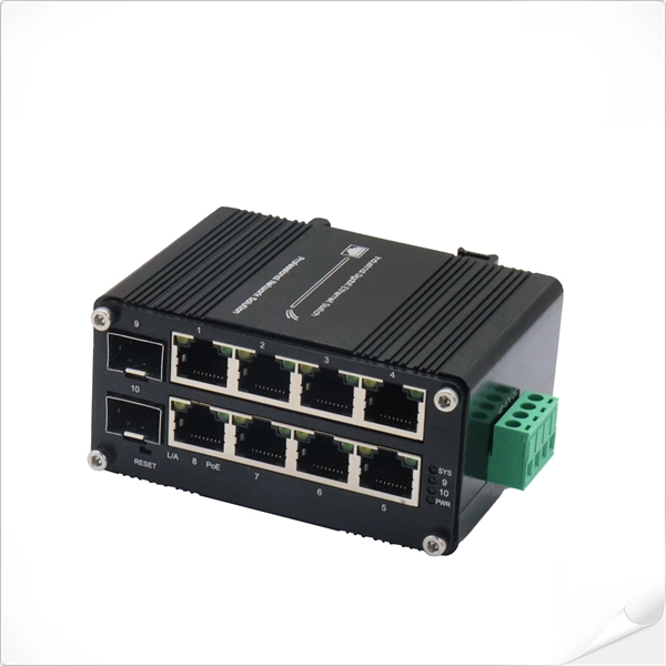
2X2 Fiber Optical Switch connects optical channels by redirecting an incoming optical signal into a selected output fiber. The 2X2 Opto-Mechanical Optical Switches consists of 2 input and 2 output fiber ports that selectively transmits, redirects, or blocks optical power in a fiber. An all-optical Ethernet switch is a network switch whose service ports are entirely optical, meaning every interface uses fiber rather than copper. This design enables end-to-end optical signal transmission, avoiding the conversion between electrical and optical signals at the switch port level. There are no specific requirements for this document. This document is not restricted to specific software and hardware versions. The information in this document was created from the devices in a. The optical ports on the switch are usually paired together, with one TX sender and one RX receiver. The. This gigabit fiber switch has 8-port 1000Mpbs SFP socket and 2ports RJ45 port. The electrical interface will Auto-Negotiate to a 10/100Mbps, or 1000Mbps Ethernet rate without any adjustments. Built on Huawei's unified software platform and equipped with high-performance fully programmable chips, they deliver abundant features including Service Roam.
[PDF]
F port is FastEthernet interface and fast Ethernet port, also known as 100M port. It is mainly used to connect switches or computers. When selecting or configuring a network switch, you often encounter ports labeled G, F, E, and S. Understanding the differences between these port types is essential for proper network design, cable selection, and optical module compatibility. Below, we break down each port type in detail. You can use commands to set bandwidth. This article will focus on the four common interfaces: G port, F port, E port, and S port to facilitate understanding before installation. S port The meaning of Serial interface is also called high-speed. S port is fully called serial interface, also known as high-speed asynchronous serial port. E port It is the Ethernet interface. Each Fibre Channel port can be used as a downlink (c onnected to a server) or as an uplink (connected to the data center SAN network).
[PDF]

It can be seen from the above that the aggregation switch has functions such as source address, destination address filtering, real-time policy, security, network isolation, and segmentation. Compared with access switches, aggregation switches have better performance and higher. What is an Aggregation Switch and How Does it Work? An aggregation switch consolidates data traffic from multiple network access switches into a single high-bandwidth link directed toward a core network or data center. The primary function of an aggregation switch is to aggregate and forward data. A fiber optic aggregation switch is a high-capacity network device designed to integrate and manage multiple fiber optic connections from access layer switches into fewer and faster uplink connections to the core network. It is essential for larger networks requiring efficient data flow. You may also. All-optical Ethernet switches are a type of switch that provides optical uplink and downlink ports, making them an ideal choice for building an all-optical campus network. They can function as core, aggregation, and access devices on campus networks and connect to upstream and downstream devices. As the physical entity of the aggregation layer, the aggregation switch's primary function is to aggregate the data of the access layer switch and forward it to the core switch to reduce the burden on the core layer. Cisco's aggregation switch What is the Role of the Aggregation Switch in the.
[PDF]

The QSFP28-100G-SR4 is a transceiver module designed for 100m optical communication applications. The design is compliant to 100GbASE-SR4 of the IEEE 802. 3-2012 Clause 88 standard IEEE 802. 100GBASE QSFP Active Optical Cable, 10m. 100GBASE QSFP Active. Each type provides information about the production during the forecast period of 2016 to 2027. Understanding the segments helps in identifying the importance of different factors that aid the market. TE SEACON is an industry leader in the design and manufacturing of underwater and subsea connectors, providing a comprehensive range of over 2,500 high-quality electrical and fiber optic connectors. The module converts 4 inputs. Global 100G Optical Transceivers Market Size By Product Type (Transceiver Modules, Active Optical Cables (AOCs)), By Interface Type (LC Interface, MPO Interface), By Application (Data Center, Telecommunication), By Transmission Distance (Short Range (up to 150m), Medium Range (up to 10km)), By Data. Modern data centers rely on high-speed optical links, and 100G optical transceiver modules (especially the QSFP28 form factor) are now foundational for this connectivity. 100G transceivers convert electrical signals to laser light over fiber, enabling top-of-rack switches to connect to aggregation.
[PDF]
Please select a category, brand, and model to find a type-approved device. Results will be displayed here after search. You can now apply and manage your RSB services online. Start today! The RSB Standards Store has a wide range of Standards covering various sectors and industries. Need help with any of your other applications? Apply for Zamukana Ubuziranenge and get assistance from our staff. Increase the. An LPO (Linear Pluggable Optics) solution offers considerable power savings for optical interconnect by removing the digital signal processing (DSP) function from the pluggable optical module. The idea is simple: instead of a DSP (digital signal processor) inside the module – replacing it with transimpedance amplifier (TIA) and a driver chip with high linearity and EQ capability – LPO shifts signal processing into. LPO (Linear-drive Pluggable Optics) is a transceiver packaging technology. It utilizes specialized components, including ASIC substrates, ASIC. In response, several solutions such as Linear Receive Optics (LRO), Linear Pluggable Optics (LPO) and Co-Packaged Optics (CPO) have been proposed. 1 shows the typical block diagram of a pluggable transceiver consisting of on-board lasers, optics, a Photonics die housing the modulator.
[PDF]
For TDM-PON, a passive optical splitter is used in the optical distribution network. In the upstream direction, each ONU (optical network units) or ONT (optical network terminal) burst transmits for an assigned time-slot (multiplexed in the time domain). In this way, the OLT is receiving signals from only one ONU or ONT at any point in time. In the downstream direction, the OLT (usually) continuously transmits (or may burst transmit). ONUs or ONTs see their own data through the address labels embe.
[PDF]
Faso, leading manufacturer engaged in R&D, optical fiber networking and telecom products. Supply all types of fiber optic cable, patchcord, distribution box, splice closure, MTP solution and FTTH solution with ISO 9001:2015, CE, RoHS certification, 10-30 years warrenty. The government of Burkina Faso has selected Bridge Fiber Solutions (BFS) to operate and manage the country"s national telecommunications backbone. The company launched its commercial activities in Ouagadougou on Friday, March 10 in the presence of the Minister of Digital Transition, Posts and. 09 BP 1725 Zaca project, Ouagadougou, Burkina Faso. +226 67054674 Structured cabling is the passive infrastructure that supports the transmission of data, voice, and video signals in a building or campus. We owned 8 technical patents.
[PDF]

Fiber optic cables use total internal reflection to keep light signals bouncing within the core, allowing data to travel quickly and with minimal loss. An optical fiber is comprised of a light-carrying core in the center, surrounded by a cladding that acts to traps light in the. Optical fibers are thin glass rods that use the properties of light reflection and refraction to transmit data over long distances. They actively shuttle data encoded in pulsing light across vast distances using only subtle differences in materials. They consist of three elements as shown in Figure 1: a central core, cladding and a protective coating. Optical fibers operate on the principle of total internal reflection, which. Refraction and total internal reflection (TIR) are the two fundamental optical principles that allow light to propagate through optical fibers over long distances with minimal loss. Understanding these mechanisms is essential for designing, installing, and troubleshooting fiber networks in FTTH. Fiber optic cables use a similar concept to guide light. Fiber optic. Describe the workings and uses of fiber optics. Analyze the reason for the sparkle of diamonds. A good-quality mirror may reflect more than 90% of the light that falls on it, absorbing the rest.
[PDF]

Key finding: This paper develops analytical models and design procedures of ultra-wideband Wilkinson power dividers using linearly tapered transmission lines (TTLs) which provide size reduction and broadband performance. Read more. Power dividers are the passive electronic equipment used for splitting the power. They are now being employed in a variety of communications applications such as telephonic, antennas configurations, mobile connectivity, internet technology, & optics, etc. They come up with very low loss, operate at. RF and microwave power splitters and dividers create two copies of the same signal, while ideally preventing crosstalk between the outputs. Doing this with minimal loss while maintaining signal integrity is a challenge. In this article we explain how power splitters work and what the tradeoffs are. The rise of wireless connectivity requirements for applications such as Internet of Things (IoT), cellular, and automotive electronics is resulting in systems that are increasingly using RF signals, components, and subsystems. Often, designers need to direct these signals to more than a single. A power divider is a passive electronic device used in radio frequency (RF) and microwave applications to split an input signal into multiple output signals with equal or specified power levels, while maintaining impedance matching to minimize signal reflection and loss. How can power dividers.
[PDF]
Several different designs are used to create birefringence in a fiber. The fiber may be geometrically asymmetric or have a refractive index profile which is asymmetric such as the design using an elliptical as shown in the diagram. Alternatively, permanently induced in the fiber will produce ; this may be accomplished using rods of another material included within the cladding. Several dif.
[PDF]