In fiber optic circuit technology an optical fiber link is used for transferring digital or analogue data in the form light frequency through a cable which has a highly reflective central core. Internally, the optical fiber.
[PDF]

The following wiring diagram shows the installation of a 60A subpanel for both 120V and 240V. You may use the current rating according to the system requirement i. 50A, 60A, 100A, 150A and so on. We have used 60A for illustration purposes only. Click image to enlarge. Primary distribution systems consist of feeders that deliver power from distribution substations to distribution transformers. A feeder usually begins with a feeder breaker at the distribution substation. Many feeders leave substation in a concrete ducts and are routed to a nearby pole. At this. An electrical sub panel, also known as a sub distribution board or sub circuit breaker panel, is a smaller secondary panel connected to the main electrical panel in a building. It serves as an extension of the main electrical panel to distribute power to different areas or circuits within a. secondary unit substation is a close-coupled assembly consisting of enclosed primary high voltage equipment, three-phase power transformers, and enclosed secondary low-voltage equipment. We have used 60A for illustration. Installing a subpanel is best handled by a professional electrician, but if you're curious how it's done, here is a brief overview of how to install a subpanel breaker box. Equipment Identify the location where you're adding a second breaker box. This information will help as you consider a Sub-Panel and its size. Electrical Tips and Be Sure to.
[PDF]

Simple 3-phase distribution board wiring diagram for home use, showing safe connection of power supply, breakers, neutral, and earth for residential electrical systems. Hey, in this article we are going to see the Three (3) Phase Distribution Board Wiring Diagram and Connection Procedure. The three-phase distribution board is used to distribute power to the three-phase loads and circuits such as three-phase motors, three-phase machinery, three-phase to. A distribution board, also known as a DB box, is like the central hub of an electrical system. It contains multiple circuit breakers and connects various electrical circuits to ensure the safe flow of electricity throughout the building. Unlike single-phase systems, where power is distributed using. When it comes to understanding the basics of electricity and wiring, a wiring diagram of a three phase distribution board is indispensable. This diagram shows how electricity is distributed in a home or building and helps you identify which connections should be made when constructing, modifying or. Welcome to our channel! In this video, we'll walk you through the process of wiring a home distribution box with a detailed connection diagram. Whether you're an electrician or a DIY enthusiast, this guide will help you understand the basics of home electrical distribution. These setups typically provide 240V for most applications, but it's crucial to follow the proper configuration to prevent hazards.
[PDF]

The 6 terminal junction box wiring diagram provides a visual representation of how the various wires and connections should be made within the box. It shows the layout and arrangement of the terminals, as well as the color coding and labeling of the wires. Hey, in this article we are going to see the Single Phase Distribution Box Wiring Diagram and Connection Procedure. A distribution board or distribution box is where the main power supply is distributed to multiple loads. It provides a quick and easy reference guide to understanding the meaning behind each symbol. These symbols can represent different electrical components, such as switches, resistors. This technical article aims to take you on a journey through the fundamental terminals and other connecting elements of wiring diagrams and electrical schematics and to delve into the minute intricacies of the components that form them. From the familiar male and female terminals that form the. An electrical panel box, also known as a breaker box or a distribution board, is a crucial component of any electrical system. Whether you're an electrician or a DIY enthusiast, this guide will help you understand the basics of home electrical distribution. more Welcome to our. The Engineering Base terminal block diagram is a special template showing information about terminal blocks, terminals and their accessories. There are two methods for creating a terminal block.
[PDF]
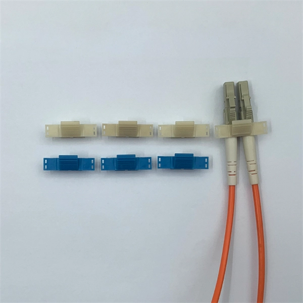
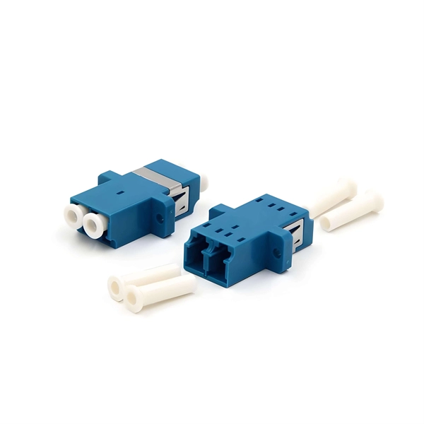
The 8 Port Fiber Access Terminal (FAT) is designed to connect feeder cables to subscriber drop cables for FTTH last-mile fiber connectivity; it can achieve direct or branch and terminal connection in FTTH or FTTB projects. FTB-SC8-WOPA type fiber optic terminal box is designed for FTTx application, which is cable to meet at least 8 users requirements. It can help splicing, splitting, storage and management with suitable space. Simple with light weight in design, special snap clip close system coinvent for user. ORCA® terminal optic box it is the best solution for indoor optical cable distribution or termination. The plastic case it is very light for a simple use. The FOTB fit the SC Simplex adapter (on request with ST and FC adapter). It is possible to buy the unloaded version (w/o Adapter) or the. Maximum capacity: 8 SC simplex, 8 LC duplex. The 8 port Fiber Distribution Box is sturdy in structure, lightweight in size, and easy to install. Built with high-density configurations and rugged materials, this MST box is perfect for installations in harsh environments like 4G/5G. The wall-mounted optic fibre termination box allows for easy organization of optic fibre cables (up to 4 fibres, depending on the installed adapters.
[PDF]

We analyzed 77 Internet of Energy startups. 2GG, Leap, Bandora Systems, Covert Science, and RESYNC develop 5 top solutions. Learn more in our Global Startup Heat Map!. With the rapid advancement of battery technology and the demand for environmental sustainability, new energy vehicles (NEVs) are becoming more and more popular. This research paper delves into the impact of marketing strategies employed by new energy vehicle companies on consumers' purchase. Under the global trend of green economy and energy conservation, the automotive industry has increasingly shifted towards new energy vehicles (NEVs). This study focused on ORA, a leading NEV brand, and aimed to analyze its marketing strategy using SWOT analysis and the 4Ps marketing theory. The. The first theme is 'Energy Market Characteristics' and deals with the experts' description of energy companies and markets, and ways in which branding has been used in the energy sector. Options for renewable sources, smart tech, and flexible tariffs put control in their hands. The result? Traditional marketing no longer wins attention or trust. The pace of transformation is relentless. Amidst the vast digital landscape, SEO acts as a guiding beacon for renewable energy brands, ensuring that their voices resonate prominently across search engines and online platforms.
[PDF]
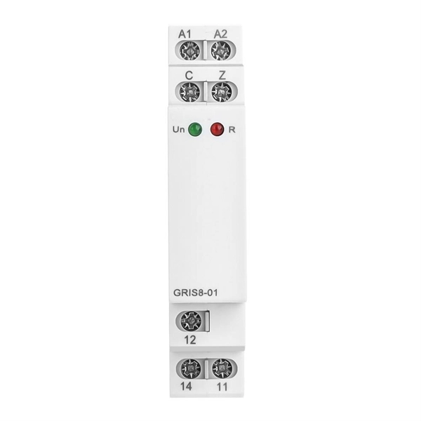
The original unstructured record data for the defect of the relay protection devices (RPDs) may contain problems influencing the data mining, and it is lack of quantitative evaluation. So the purpose of this.
[PDF]
Market Size by Fiber Type, by Deployment, by Cable Type, by End Use Industry – Global Forecast. The global fiber optic cable market was valued at USD 13 billion in 2024 and is estimated to grow at a CAGR of 10. The Fiber Optic Cable Market Report is Segmented by Cable Type (Armored Cable, Non-Armored Cable, and More), Fiber Mode (Single-Mode Fiber, Multi-Mode Fiber, and More), Installation Type (Aerial/Overhead, Underground/Buried, and More), End-User Industry (Telecommunication, Power Utilities and Smart. The global Fiber Optic Cable Market is anticipated to be worth USD 5. It is expected to grow steadily and reach USD 11. This growth represents a CAGR of 7. 21% during the forecast period from 2026 to 2035. I need the full data tables, segment breakdown, and. The fiber optics industry is projected to reach USD 6. 8 billion by 2029 from USD 3. Rapid expansion of data centers, cloud services, and 5G infrastructure is driving strong adoption of fiber optic solutions. 64% between 2023 and 2028. The market is experiencing significant growth, driven by the increasing demand for high-speed internet connectivity and the expansion of data centers.
[PDF]
There are several diagnostic methods to help troubleshoot fiber optic connectors, and the diagnostic method is to cross-section the fiber optic connector. This technology allows us to actually look inside the fiber optic connector to see defects and pinpoint the cause of. Fiber design and transmission technology have collaboratively evolved to increase bandwidth. Dig-ups dominate! Cablers have very little influence on the majority of causes of cable field failures. While a small percentage, we can examine the “intrinsic” cable failures and what is done to prevent. Connector failure is most frequently the result of a dirty or damaged end-face. Fiber-optic connector: SC type In the connector, the element that holds the fiber and provides the alignment positioning is the ferrule. The. In August of 1999, Boeing Corporation (Boeing) engineers being used on International Space Station flight a defect in the glass fiber (see Figure 1, “Rocket and NASA engineers and managers, Boeing created and reliability of the cable installed in the U. Fiber coupling can be accomplished by fusion splicing.
[PDF]
This comprehensive guide breaks down the internal structure, core components (TOSA, ROSA, lasers), and operational mechanisms of SFP optical modules, enriched with technical insights and real-world applications. As core components for photoelectric conversion in optical communication systems, data center interconnection, and long-haul transmission, optical modules rely on TOSA and ROSA to realize high-speed signal conversion. Now, ETU-LINK will introduce to you the components of the optical module— TOSA. TOSA, ROSA, and BOSA are critical components in optical transceivers. These modules play a vital role in transmitting and receiving optical signals. TOSA ( Transmitter Optical Sub-Assembly), converts electrical signals into optical signals for transmission. OSAs generally fall into three main categories: TOSA, ROSA, and BOSA. • TOSA TOSA: Transmitting Optical Sub-Assembly. First of all, the two most important parts of the optical module are the Transmitter Optical Subassembly (TOSA) and the Receiver Optical Subassembly (ROSA).
[PDF]
This report studies the global Optical Communication Module production, demand, key manufacturers, and key regions. The global Optical Module For Communication market size was US$ million in 2024 and is forecast to a readjusted size of US$ million by 2031 with a CAGR of %during the forecast period 2025-2031. 7% during the forecast period MARKET INSIGHTS The global Active Optical Module Market was valued at 5916 million in 2024 and is projected to reach US$ 15140 million. Major optical modules manufacturers and suppliers: Innolight, Eoptolink, Huagong Tech, Linktel, Accelink, CIG ShangHai CO. Upstream optical devices manufacturers and suppliers: TFC, T&S Communications, Advanced Fiber Resources, Borui Technology, Optowide Technologies. Upstream optical chips. Global Optical Modules Market Size By Product Type (Transceivers, Transponders), By Technology Type (Single-Mode Fiber (SMF), Multi-Mode Fiber (MMF)), By Application (Telecommunications, Data Centers), By Data Rate (10 Gbps, 25 Gbps), By Form Factor (SFP (Small Form-Factor Pluggable), SFP+. Additionally, strategic partnerships and acquisitions are prevalent, enabling companies to access new technologies, markets, and expertise. Market Share Analysis: Product Portfolio: Offering a comprehensive range of solutions across different segments, from access networks to long-haul.
[PDF]
Welcome to our channel! In this video, we'll walk you through the process of wiring a home distribution box with a detailed connection diagram. It serves as a central hub for distributing electricity throughout a building, ensuring that power is delivered safely and efficiently to all the required locations. And all the switching and protective devices are installed in the. Distribution Board or DB is an electricity supply system or a common enclosure that distributes the electrical power feed into subcircuits. It includes isolator, RCCB (Residual current circuit breaker) or RCD (Residual-current device) devices, protective fuses or MCB's (Miniature Circuit Breaker). That's why having a clear, detailed diagram of your home's distribution board wiring is essential. A distribution board (also known as a service panel or breaker box) is a centralized collection of circuit breakers, fuses, and/or relays used to control and protect the wiring in a home.
[PDF]

In this guide, you will learn how to interpret network diagrams like a pro, from symbols and scope to segmentation, dependencies, troubleshooting, and security clues. A rack elevation diagram is a visual representation of the equipment and components contained within a rack in a data center or server room. It provides a clear overview of the physical layout of the rack, including the placement and positioning of servers, switches, storage devices, and other. Learn how to read and interpret network diagrams effectively to troubleshoot, validate security, and plan network changes with confidence. Have you ever opened a network diagram and felt like you were staring at a subway map with no station names? That is a common problem, even for experienced IT. Network cabinet cabling describes the structured connection and arrangement of all IT components in a server rack. The aim is a secure, maintainable and scalable operation of the network environment. The amount. A standard operating procedure, or SOP, is a set of step-by-step instructions compiled by an organization to help workers carry out complex routine operations. Work instructions should be very detailed on "how" to accomplish a specific job, task or assignment. It helps teams understand network architecture, data flow, and dependencies, making it easier to design infrastructure, troubleshoot issues, and plan.
[PDF]
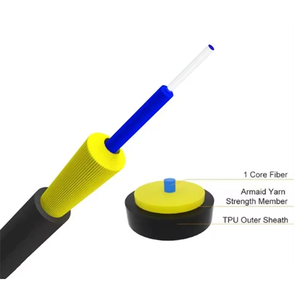
Figure 1 is a diagram of the basic construction of both loose-tube and tight-buffer fiber optic cable. An optical fiber cable is a complex structure designed to protect fragile glass fibers that transmit digital data using light signals. This advanced cabling solution allows fast, secure data transfer and telecom over long distances. Understanding the components within a fiber optic cable enables. A fiber optic cable consists of five basic components: the core, the cladding, the coating, the strengthening fibers, and the cable jacket. When searching for a fiber optic cable, we need to pay attention not only to the connectors, such as SC to ST fiber cable, LC to SC fiber patch cable, or SC to. Optical fibers are circular dielectric wave-guides used to contain and transmit light over short or long distances. They consist of three elements as shown in Figure 1: a central core, cladding and a protective coating. Understanding its internal structure is essential to appreciate how it functions efficiently in various applications, from telecommunications to medical devices. The core is the. 3,260 optical fiber structure illustrations, drawings, stickers and clip-art are available royalty-free for download. Multimode all-media self-supporting fiber optic cable structure isolated on white. More specifically, we can say that it is a waveguide that has the ability.
[PDF]

Distribution box The system diagram usually shows the electrical connection and configuration inside the distribution box in a graphical way, including busbars, circuit breakers, fuses, load devices and other elements. In practical applications, the corresponding system diagram can be drawn. A wiring diagram symbols chart is a visual representation of the various symbols used in electrical diagrams. It provides a quick and easy reference guide to understanding the meaning behind each symbol. These symbols can represent different electrical components, such as switches, resistors. Hey, in this article we are going to see the Single Phase Distribution Box Wiring Diagram and Connection Procedure. A distribution board or distribution box is where the main power supply is distributed to multiple loads. Understand its role in electrical systems and safety. It helps control and distribute electricity to different areas. Inside. In the world of electrical installations, the term DB box —short for Distribution Board box —refers to the central unit that distributes incoming electrical power to multiple outgoing circuits in a building. Whether you're powering up a residential home, a commercial office, or an industrial plant. Power distribution panel is used for utilization of equipment. A molded case circuit breaker are used which incomer supply is connected with LT panel and outgoing supply is connected width panel busbar.
[PDF]


